by Camille | Robots, Workshop Blog
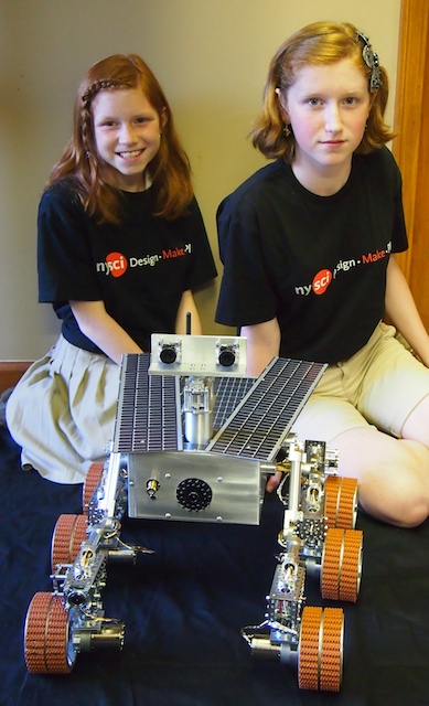
We have exciting news to share. A short time ago the New York Hall of Science contacted us. They have a large and beautiful Mars exhibit, but their existing robot is outdated and needs to be replaced. After some discussion about their requirements, we agreed to build them a new fully-functional Mars Rover robot for their exhibit. You may have noticed that we’ve been chronicling our work on the new rover in our Workshop Blog for the last several weeks. We have done most of the metal machining, mechanical assembly, electrical soldering, electronics wiring, and other work on the project. They will also be part of the on-site testing and installation in New York. Update: We installed the Mars Rover at the New York Hall of Science on June 8, 2013. It has been a great success so far. It has become the science center’s most popular exhibit.
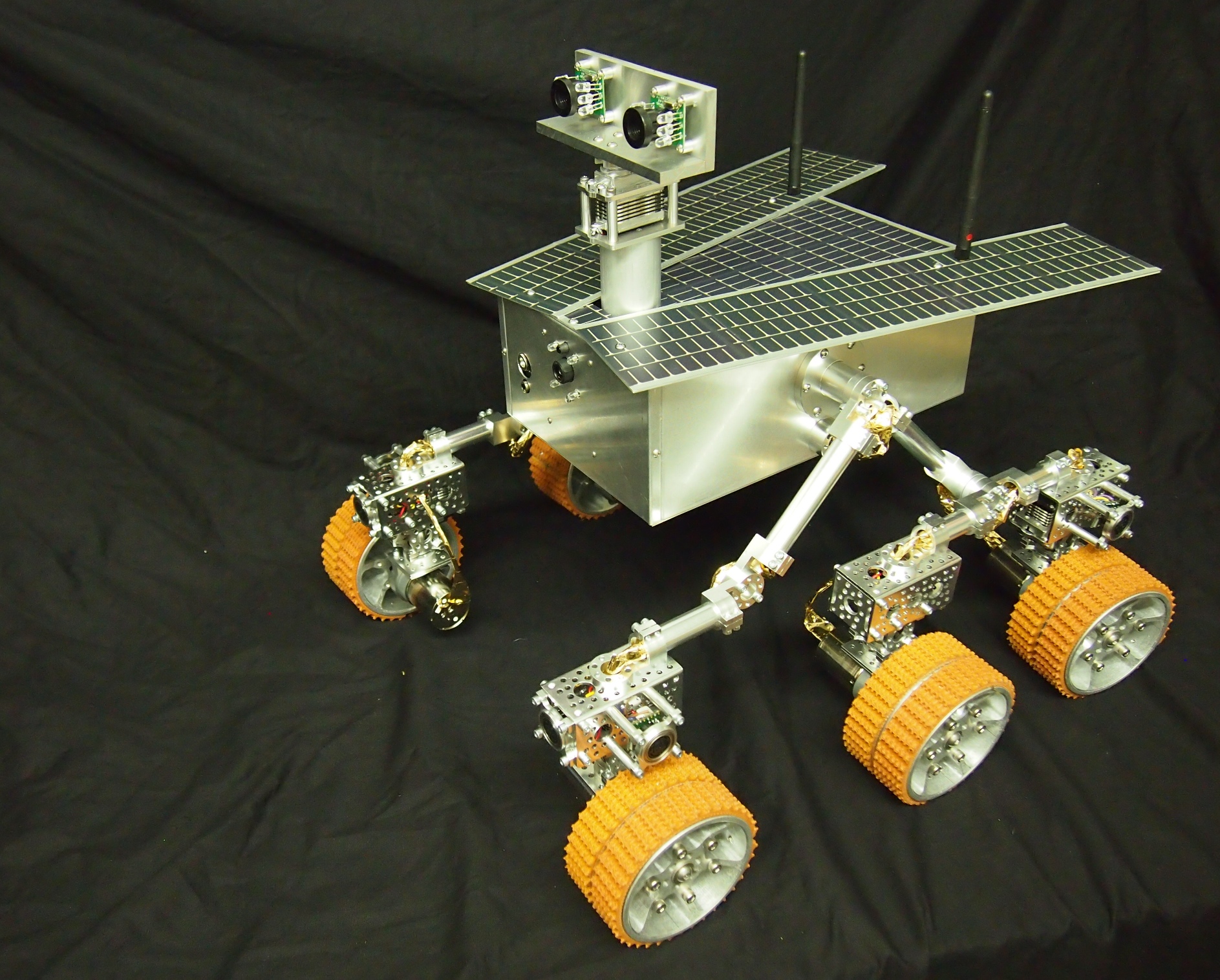
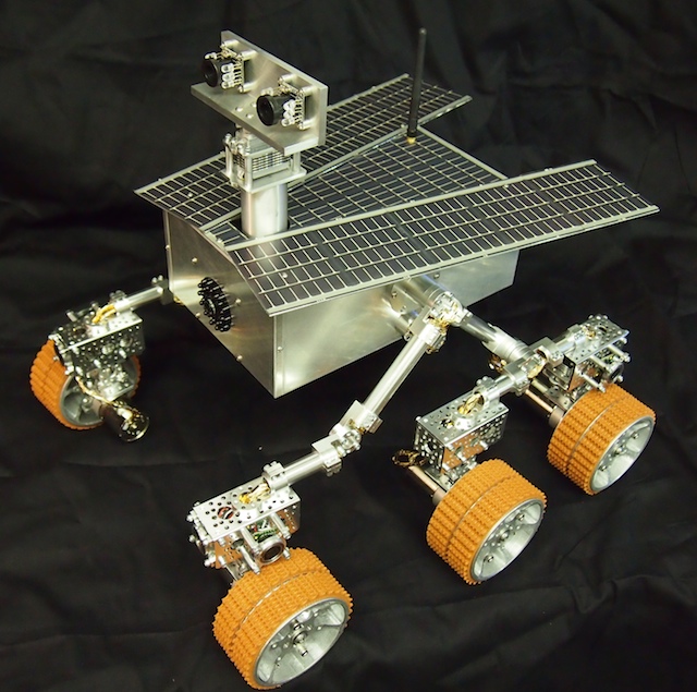
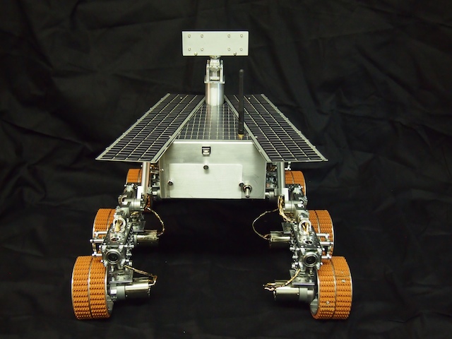
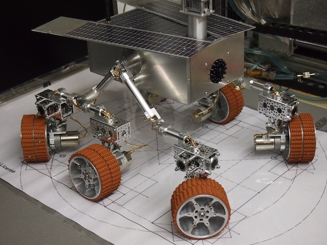
The Mars Rover is constructed of over 700 electrical components, aluminum parts, and other pieces that we purchase, make by hand, and/or machine on our homemade CNC Mill. In addition to the NASA-style six-wheeled rocker-bogie suspension system and the solar panels, the new Mars Rover is equipped with an infrared camera, a thermal array sensor, eight sonar sensors, and other technology. Using special control software that we will provide, kids and other visitors to the center will drive the Mars Rover remotely through the exhibit’s Mars-scape on a mission to find infrared-emitting rocks that may provide evidence of past life on Mars.
With over 450 interactive exhibits, the New York Hall of Science is the largest collection of hands-on science and technology exhibits in the New York City area, and rated as one of the best science centers in the country. They are actively involved in pioneering the Design/Make/Play revolution. Built initially as a pavilion for the 1964 World’s Fair, the New York Hall of Science is not only the region’s premier science museum, it hosts the world-renown New York Maker Faire each fall. We are honored to be working with the NYSCI and we’ve been having great fun (and many hours of hard work) building what we hope will be an excellent robot for them.


OUR POSTS ON THE CONSTRUCTION OF THIS ROBOT:
Our new Mars Rover Arduino Shield
Soldering the Mars Rover Shield
Mars Rover – Adding the Targeting Laser and Thermal Array Sensor
Mars Rover – Mast and Solar Panels
Continued work on the Mars Rover
Mars Rover – Infrared Detection
Making progress on the Mars Rover
Mars Rover – Electronics
Major milestones reached on the Mars Rover
Using CNC to machine the electronics plate for Mars Rover
Cutting metal for the Mars Rover 2
A Counter-rotating Differential
POSTS RELATED TO OUR ORIGINAL PROTOTYPE:
https://beatty-robotics.com/spirit-ii-mars-rover/
Spirit II – Mars Rover: INSIDE VIEW
Solar Power System
Differential for Mars Rover
by Camille | Workshop Blog
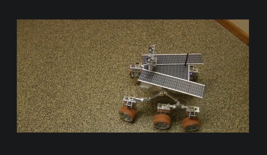
In the video below we have documented our first “basic motion test” on the new Mars Rover. Using our radio-based handheld remote control, we are testing the forward, backward, and rotation of the robot to make sure that it moves smoothly and correctly. We then test the NASA-style rocker-bogie suspension system. The purpose of the rocker-bogie suspension system is to allow the robot to drive over obstacles (such as rocks) and remain relatively steady even if the obstacle is only on one side. The front wheel goes over first while the two back wheels remain firmly on the ground (rotating on the swivel-hub of the rocker-bogie hub, which is between the two back wheels). Once the front wheel is firmly on the ground again, the rocker-bogie on the back goes over the obstacle, one wheel and then the next.
You may also notice a green laser on the robot. The green laser indicates the scan region for the thermal sensor. The robot reports eight temperatures from left to right where ever the laser is pointing. This will be used by science center visitors to scan and identify targets in the exhibit. The results of this first test are described below the video.
The Mars Rover by Beatty Robotics from Camille & Genevieve Beatty on Vimeo.
Overall, the robot performed extremely well in its first motion test. The motors and wheels ran very quietly and smoothly with no noticeable issues, both forward and backward. The steering servos turned correctly and rotated the robot on command in both directions. The robot traveled smoothly with no noticeable noises, vibrations, or problems. All the tubes, screws, hubs, joints, and other components remained in place and performed their function. Mechanically, the robot met all requirements during the motion test.
We noted that the rocker-bogie suspension system worked very well, but as expected, it behaved a little bit differently compared to the first Mars Rover we built. On the first Mars Rover we installed a counter-rotating differential gear box in the central shaft of the robot. When one of the front wheels goes over an obstacle and that side of the robot lifts up, then the other side of the robot is pushed down in the opposite direction (keeping the main box more level). The exhibit at the New York Hall of Science is flat, so we won’t be doing any rock-hopping, so we didn’t install a counter-rotating gearbox (we wanted to keep the design simpler and easier to maintain over time). This means that when one wheel of the robot goes over a large obstacle, both sides lift up instead of just one side. However, overall, the rocker-bogie suspension system still works very well. In fact, because it is more rigid and less gangly, the robot is rock solid, very steady when traveling and when being picked up, and there appears to be no detrimental effects to the simpler design.
There are two known issues at this time that we need to work on: 1. Sometimes when the rover stops, the digital servos (which are known for being jittery) take quite a while to find an equilibrium and settle down. Sometimes they jitter/wiggle when the robot is at rest. This is not a critical problem, but it wastes battery power and we want to improve this situation. 2. The eight sonar sensors, which are intended to measure the distance to the nearest object in the direction of travel, are reporting erroneous distances. This is a critical problem that needs to be resolved, otherwise the robot may run into things when it is driving autonomously. We are working on that now.
by Camille | Workshop Blog
A few subscribers have asked about laser and the thermal array sensor on the new Mars Rover, so this post is dedicated to that:
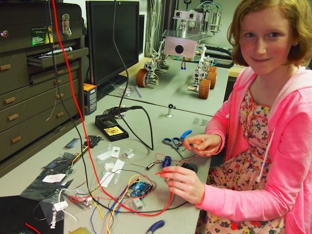
We needed to add a targeting laser and a thermal array sensor to the Mars Rover robot, so we experimented with different wavelengths of lasers and types of lenses. After looking at the results of our tests, we decided on a 532 nanometer laser (which is bright green in color), with adjustable 5 to 25 milliwatts of power, and a 38-degree line-generating lens.
We plan to use a TPA81 Thermopile Array sensor to scan the temperature of the objects that are out in front of the robot (a few feet or a few yards away). This particular sensor provides an 8 x 1 array of eight temperatures corresponding to eight points from left to right in front of it (about 40 degrees across). But it’s hard to tell exactly where it’s pointing and which objects it’s measuring, so we plan to use the laser to identify the scanning zone. We cobbled together a prototype and our initial tests of all this worked well, so we moved into the final build stage and mounted it into the robot. The key was to make sure that the laser was lined up with the thermal array sensor, which necessitated a special mounting mechanism.
Here I am with a devilish grin as I experiment with different types of lasers. I decided on the green laser because it’s strongest, easiest to see, and “just plain the coolest.”

I used my favorite tool, the vertical mini mill, to do some machining to modify the laser mount. We then drilled and tapped various threaded holes into the mount.

Here is the finished Laser Mount. The laser fits in the large hole in the middle and is held with a set screw through the threaded hole on the side. The threaded hole on the bottom is used to attach the mount to the articulating arm. The threaded hole on the face (top in the picture) of the mount is used to attached the Thermal Array Sensor. This way the Laser and Thermal Array Sensor are screwed together and always pointing in the same direction/angle.

Here we have mounted the Target Laser (on top) and the Thermal Array Sensor (on the bottom) into the front of the robot (front plate removed). You can’t see it too clearly in this picture, but the laser mount sub-assembly is mounted on an articulating arm on a base so that we can adjust the pointing angle/direction. Please note that the line generating lens is tilted in this picture and needs to be adjusted so that the visible lines in the lens are vertical (which is weird because it generates a horizontal line).
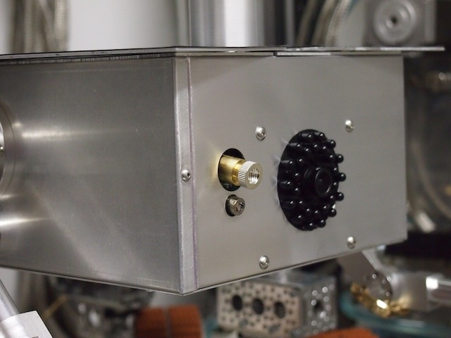
The finished result. We’re ready to scan some alien Martian life ! (Or at least some warm rocks!) 🙂
by Camille | Workshop Blog
We’ve been busy working on the new Mars Rover. Over the last few days we’ve been focused on the chassis, the thin-film solar panels for the top, the mast, and aligning the servos for steering. Pics below.
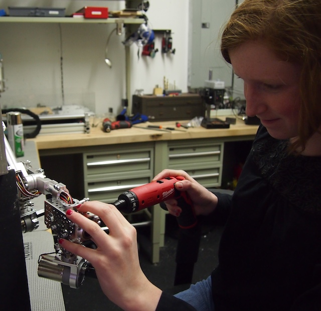
Here I am using my new power driver to work on the robot’s chassis. This is now my favorite tool.
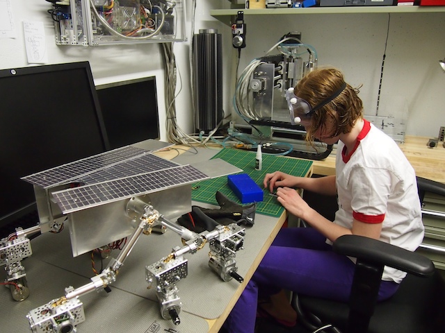
Working on assembling the solar panels that will cover the top deck of the Mars Rover.
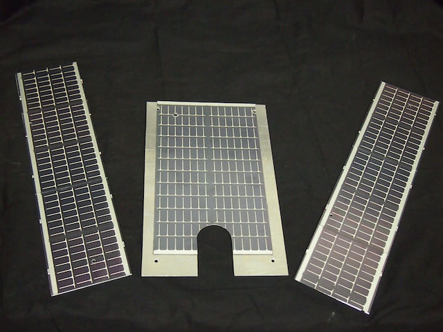
The completed “solar wings” and top deck. These are actual thin-film solar panels attached to custom-machined aluminum plates.
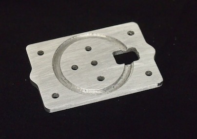
We ran into a particular challenge when it came time to build the mast. In the end, we decided to design and machine a custom servo plate using the CNC. The top of the plate will hold the pan servo. The bottom of the plate will hold the shaft tube (using a circular slot).
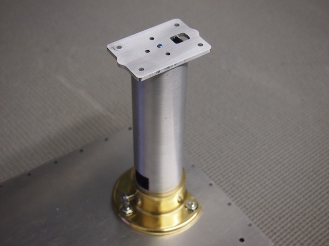
The custom servo plate mounted on the mast. The plate is held down with a threaded rod that goes down through the mast and threads into the bottom of the rover.
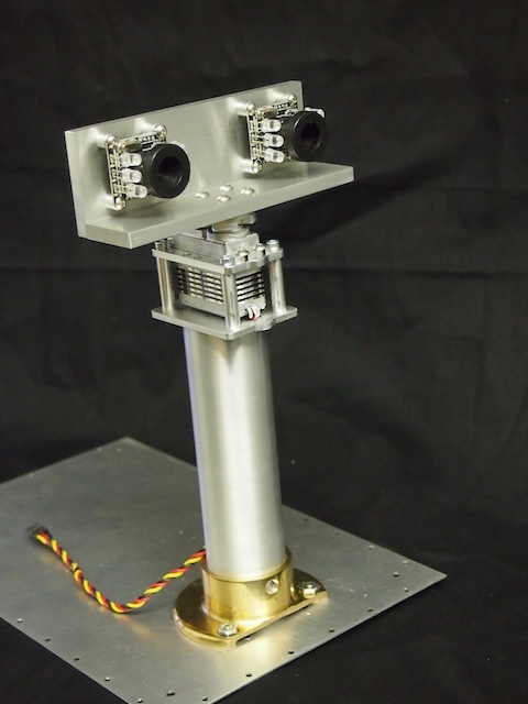
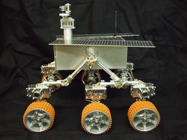
Here is the completed mast assembly. From the bottom up: The robot’s bottom plate, the mast flange, the mast tube, the custom servo plate, the pan servo, the top servo plate, the servo horn, and the mast head, which is made out of two custom machined plates of aluminum.
In order to align and calibrate the steering servos we created a special, full-scale drawing that indicates where the wheels should be at each of the various steering positions. This really helped center the servos properly.
