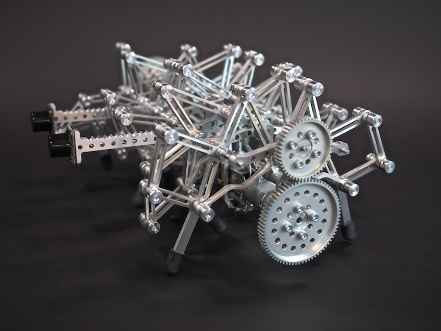
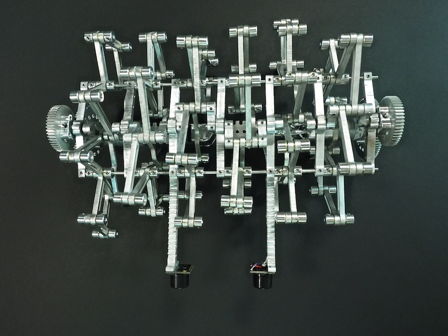
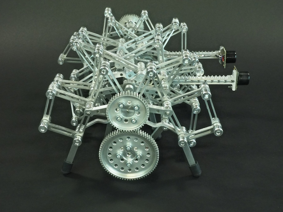
We would like to introduce you to our newest robot. Her name is Alumini, which is pronounced Ah-lu-min-ee. She’s a 12-legged running creature. She’s made out of custom, CNC-machined aluminum components designed to be like vertebrae and bones in keeping with the idea that is a creature not just a machine. Our goal was to create a little beastie without any visible wires or electronics (other than her sonar eyes). She does not have a box filled with electronics like our other robots. We wanted her to look like she was all legs. This meant we needed to use very small electronic parts and we had to do some very tricky wiring. The soldering on this project proved to be quite a challenge, but we were happy with the end results. Alumini is ten inches wide and consists of over 500 parts. Like her much larger 16-legged predecessor, Aluminalis, she uses gear motors to drive two crankshafts, one for each side. Alumini uses a tiny Arduino Pro Mini 328 microcontroller. She can operate via remote control (using an on-board xbee radio) or autonomously using her sonar eyes.
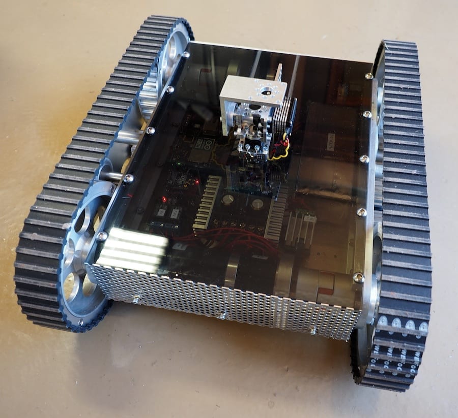
We are working on a tank with treads and a laser cannon gun turret. It’s a complex, long-term project with lots of CNC-machined parts as well a a variety of purchased components, but we’ve been making good progress on it. Today’s posting will focus on the base, which holds the electronics, provides mobility, and establishes a sturdy platform for the gun turret (not shown here).
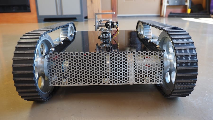
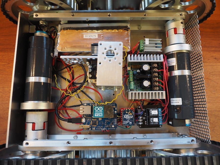
The robot is powered by a large 8-cell 30 Volt LIPO battery, our first ever. So we’ve got lots of power for the motors and the laser cannon. We are driving the wheels (which are actually timing wheels) with two beefy gear motors and a Sabertooth dual 32-Amp Motor Controller. The treads are timing belts. There are two machined aluminum plates (separated by standoffs) on each side that provide the mounting for the wheels. We are using an Arduino Yun for the first time in this robot, which is a new microcontroller that integrates Linux and Arduino into a single board, which among other things, provides for a nice wifi layer, including WiFi-based software updates. We’re using an AnyVolt voltage regulator to bring some of the 30V down to 7.4V for the gun turret servos and the laser cannon. And we have a second voltage regulator for the 5 volt components. The Arduino will trigger relays (shown) to turn on the four targeting lasers and the main laser cannon (not shown), which will laser-burn targets using an autonomous targeting system. This photo also shows the four multi-tapped rails that we made to hold the robot together, including the track sub-assemblies on each side, the bottom plate, and top plate. The front plate and rear plate are held onto the bottom plate with six small #6-32 angle brackets. To better visualize the scale of this robot, the bottom plate is about 10″ wide and 13″ long.
The CNC-machined back plate includes the main power switch, a USB jack for programming (although we’ve been using the Yun Wifi for that), banana plugs for charging, and a fuse.
There are many things we like about this robot so far, but we were especially pleased with the smoke-gray acrylic top that we machined on our CNC. It’s transparent enough to see the circuit board lights on the electronics, but opaque enough to give it a nice blackish sheen. The main top plate is held onto the rails with a bolt pattern of ten 1/4-20 bolts. The difficulty with gun turrets is that you can’t get the top plate off the base without removing the gun turret, which is a pain, so we machined a slot into the main top plate. We didn’t want to use fasteners or a hinge on the acrylic, so we machined mating shelves (grayish area along the edge) so that the small back plate press fits perfectly into the top plate and stays there without needing any fasteners.
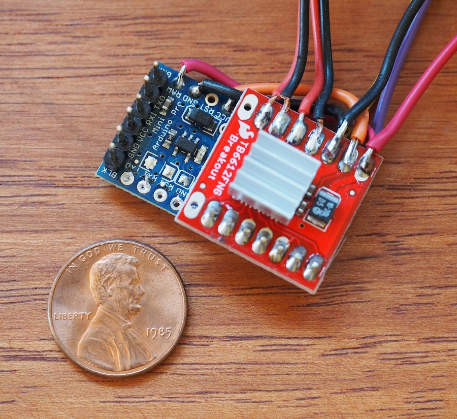
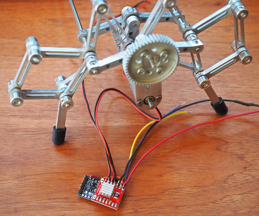
Recently, we encountered a situation where we needed a very small Arduino microcontroller and motor driver. On Alumini, our 12-legged walking robot, there won’t be an electronics box, so we will be integrating the electronics into the bones of the creature. Our goal was for the creature to appear to be all legs. So, we needed the electronics to be very small, hidden beneath and between the robot’s many leg linkages. After trying a few experiments with different components and approaches, we’re excited about the approach we came up with. We don’t know whether it’s going to work in the final robot yet, which is still under construction, but so far it seems promising. The Arduino Pro Mini board from Sparkfun is just 0.7″ x 1.3″ and it’s on a 0.032″ thick circuit board, so it’s a very small, thin little microcontroller indeed. We love the form factor. If it works on this project, it may just become our “go-to” microcontroller for small projects. We also decided to try Sparkfun’s tiny 1A Motor Driver, which is only .8″ x .8″ square.
Genevieve and I soldered up the boards and they’re working well so far, but the one negative we’ve encountered is that the motor driver is a very simple little thing. It’s basically just a breakout board for the TB661FNG chip, so it doesn’t have a lot of on-board smarts. Instead of a single TTL serial wire like we’re used to, it requires 2 PWM pins and 5 digital pins to control it. We don’t have a lot of room for wires, so we did something we thought was really cool: we sandwiched the boards together and turned the motor driver into a tiny make-shift shield for the Pro Mini board. We lined up the pins just right, wrote the software to correspond to those pins, and literally soldered the boards together, which eliminated the need for the 7 control wires. We thought there was a fair chance we would ruin the two boards, but it worked like a charm. In the photo, the seven solder points near the penny (on the red board) are the control pins between the arduino and the motor driver. The other wires (at the top of the photo) go to the 11.1V LIPO battery, motors, sonar sensors, xbee radio, and other components of the robot.
The next big question is whether this little motor driver, which is rated at 1.2A per channel can handle Alumini’s 20mm x 42mm metal gearmotors, which are rated for a free-run current of 0.25 Amp and a stall current of 3.3 amps. Normally we would use a 5A motor controller for these motors, but the 5A motor controller was too large to fit on Alumini’s delicate frame. Once we had soldered our mini robot control system together, we were able to do some testing. When we run the partially-completed Alumini robot on the bench, the motors are pulling .6 Amp each, but they don’t have much force on them yet. We’ll see how this goes once we get Alumini scuttling at high speed around the room. We may end up smoking the motor driver and going back to the drawing board. We thermal-pasted a tiny aluminum heat fin to the chip to help dissipate the heat. We’ll keep you posted.
If you know of any small microcontrollers and motor drivers that would be good for our purpose, please let us know. We would love to know how you’ve solved these problems on your projects.
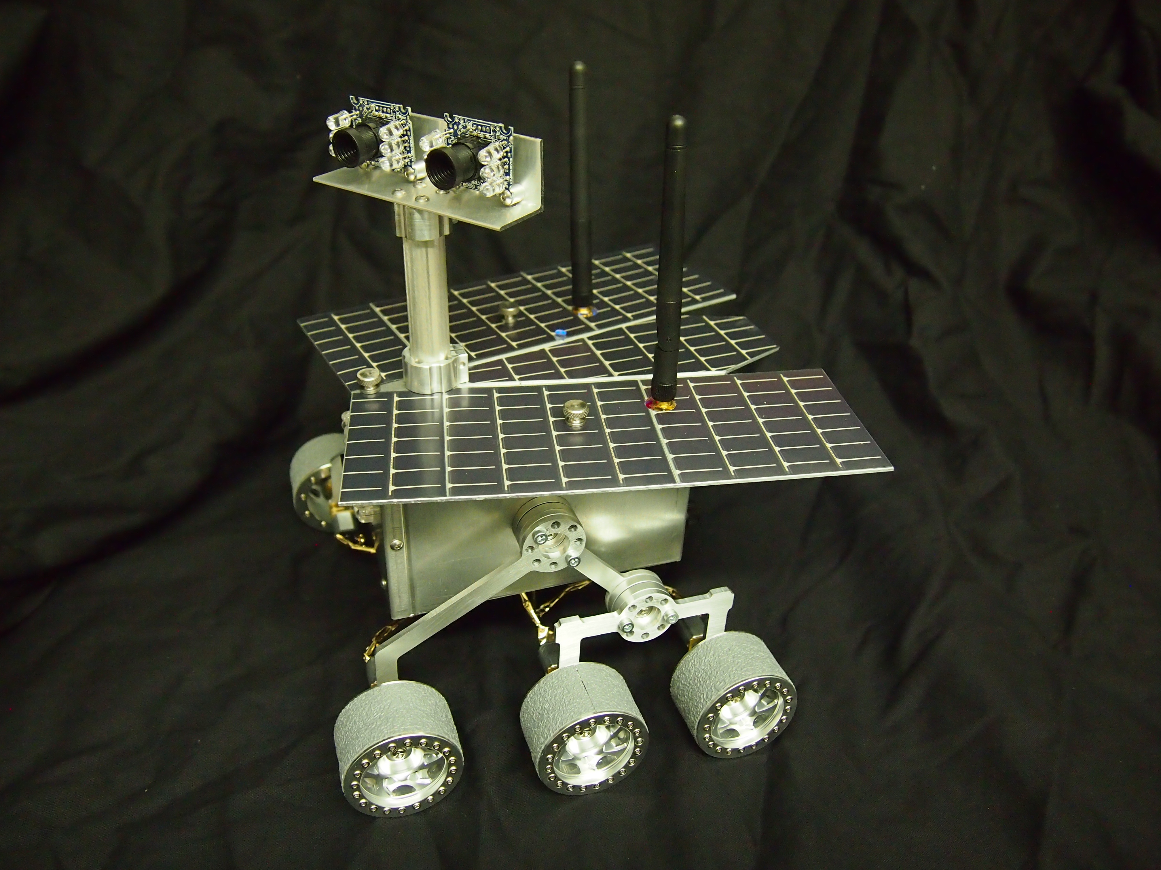
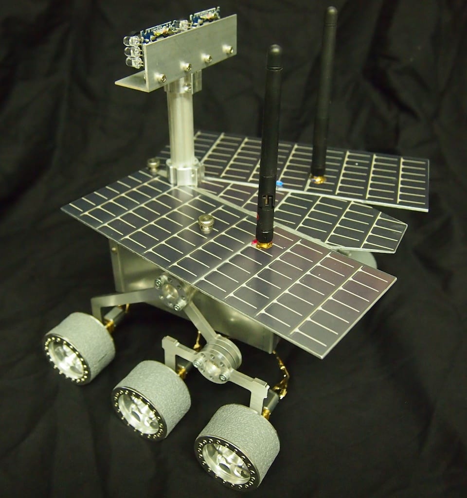
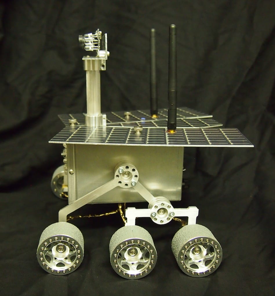
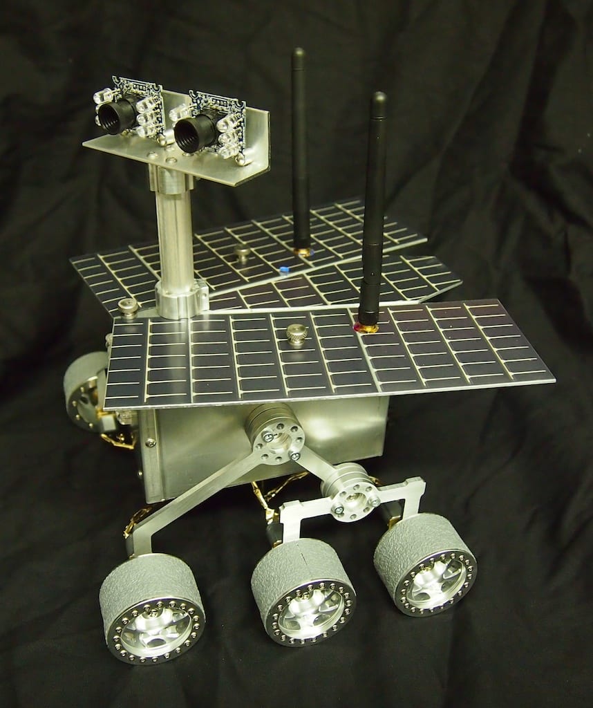
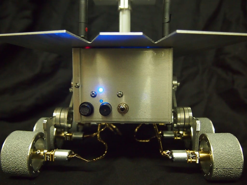
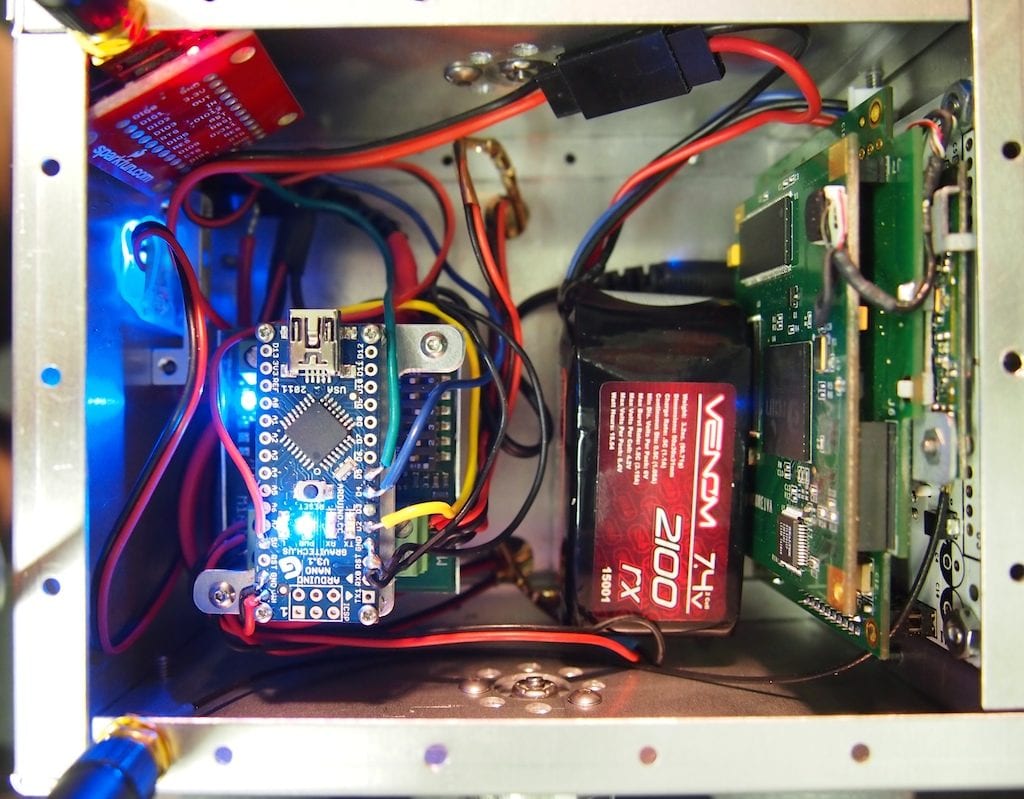
Recently we were asked to build a miniature Mars Rover for a new space museum in the Czech Republic. Although the Mini Mars Rover is only about 8″ long, it is a functional robot, including an Arduino Nano microcontroller, a high-resolution wifi camera, an xbee radio for remote control, a Sabertooth motor controller, six motors, a rocker-bogie suspension system, and other components. We designed and machined most of the robot’s parts using our CNC Mill.
Mini Mars Rover – Top Rear View
Mini Mars Rover – Side View
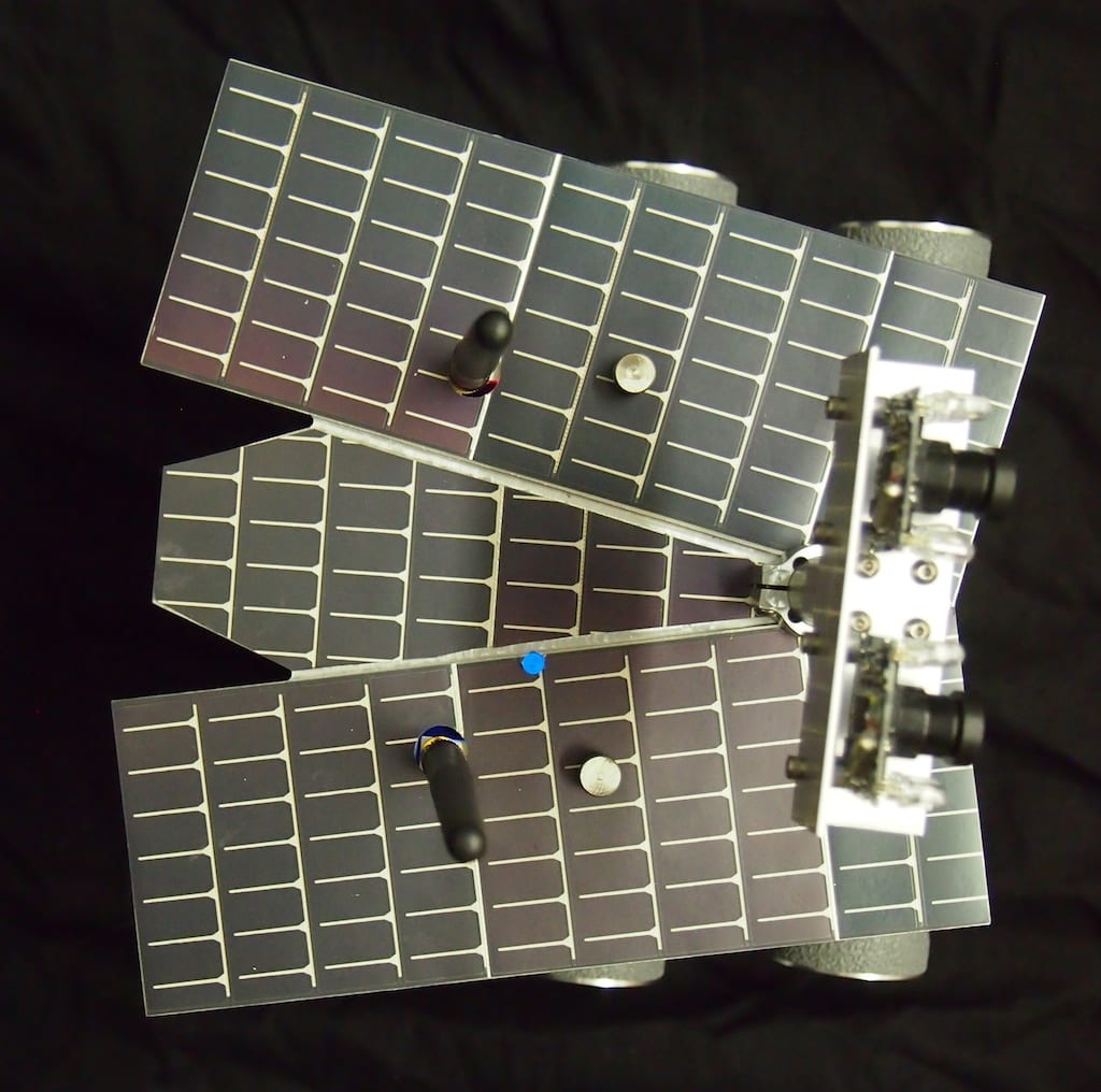
Mini Mars Rover – Top View
Mini Mars Rover
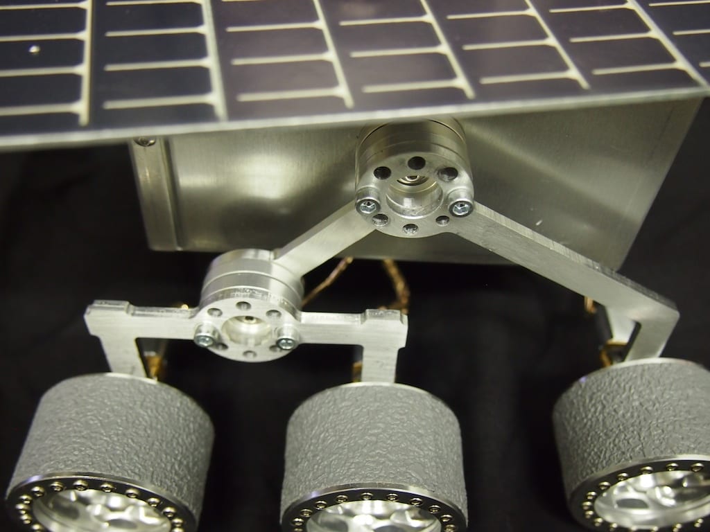
Mini Mars Rover – Rocker-Bogie Suspension System Close Up
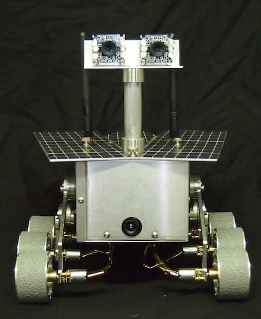
Mini Mars Rover – Front View
Mini Mars Rover – Rear View
Mars Rover Top Plate immediately after it has been CNC machined but before the solar panels have been applied.
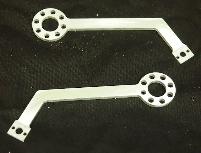
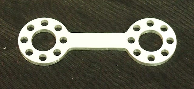
Front Arms with motor mounts
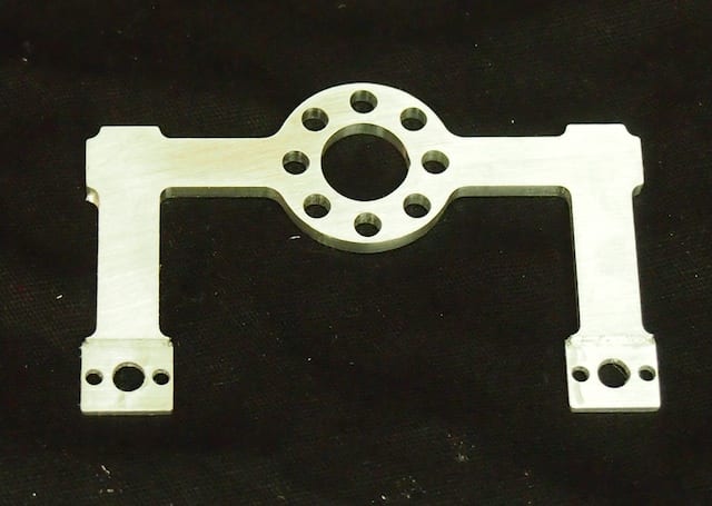
Rear Arm
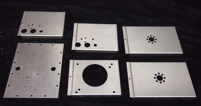
Mini Mars Rover Back Plate, Bottom Plate, Front Plate, and Side Plates. The newer version has a smaller hole for the camera.
Here at Beatty Robotics, we have a keen interest in mixing cool, old technology with exciting new technology. Recently, we became interested in Morse Code and telegraph equipment. We began exchanging written secret messages in Morse Code. And then we continued on by learning to tap the codes with rocks and listen to them at some distance. We are still learning and practicing, but it’s pretty clear that they are getting better and better and will soon be fluent. So now we’ve embarked on our next project, which is to build a functioning telegraph system by refurbishing several very old, antique telegraph keys and sounders, and then combining then with our modern electronics knowledge. We aren’t ready to show the completed project quite yet, but here are some pics of us wiring up the electronics. As we complete the project over the next few weeks, we’ll post pictures of the complete telegraph system (we’re hoping it’s going to look pretty cool), an explanation of how it all works, and the list of components.
Genevieve solders the headers on the Arduino Nano while I wire up the screw terminal board
I power up our wireless Xbee LCD screen to see if test messages are being transmitted properly from the Telegraph key. (The telegraph system itself won’t include an LCD screen. This was just for a test.)
Working together on some delicate soldering on the main microcontroller