Recently, we encountered a situation where we needed a very small Arduino microcontroller and motor driver. On Alumini, our 12-legged walking robot, there won’t be an electronics box, so we will be integrating the electronics into the bones of the creature. Our goal was for the creature to appear to be all legs. So, we needed the electronics to be very small, hidden beneath and between the robot’s many leg linkages. After trying a few experiments with different components and approaches, we’re excited about the approach we came up with. We don’t know whether it’s going to work in the final robot yet, which is still under construction, but so far it seems promising. The Arduino Pro Mini board from Sparkfun is just 0.7″ x 1.3″ and it’s on a 0.032″ thick circuit board, so it’s a very small, thin little microcontroller indeed. We love the form factor. If it works on this project, it may just become our “go-to” microcontroller for small projects. We also decided to try Sparkfun’s tiny 1A Motor Driver, which is only .8″ x .8″ square.
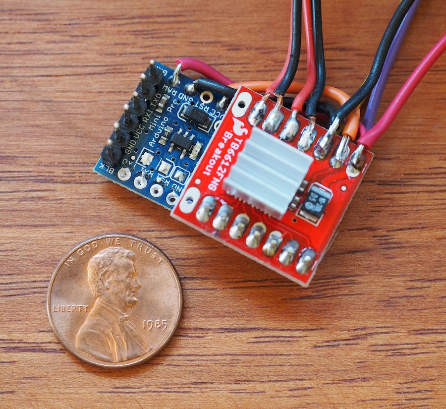
Genevieve and I soldered up the boards and they’re working well so far, but the one negative we’ve encountered is that the motor driver is a very simple little thing. It’s basically just a breakout board for the TB661FNG chip, so it doesn’t have a lot of on-board smarts. Instead of a single TTL serial wire like we’re used to, it requires 2 PWM pins and 5 digital pins to control it. We don’t have a lot of room for wires, so we did something we thought was really cool: we sandwiched the boards together and turned the motor driver into a tiny make-shift shield for the Pro Mini board. We lined up the pins just right, wrote the software to correspond to those pins, and literally soldered the boards together, which eliminated the need for the 7 control wires. We thought there was a fair chance we would ruin the two boards, but it worked like a charm. In the photo, the seven solder points near the penny (on the red board) are the control pins between the arduino and the motor driver. The other wires (at the top of the photo) go to the 11.1V LIPO battery, motors, sonar sensors, xbee radio, and other components of the robot.
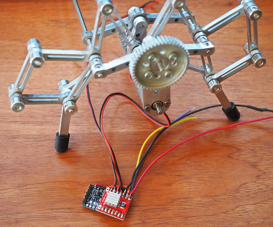
The next big question is whether this little motor driver, which is rated at 1.2A per channel can handle Alumini’s 20mm x 42mm metal gearmotors, which are rated for a free-run current of 0.25 Amp and a stall current of 3.3 amps. Normally we would use a 5A motor controller for these motors, but the 5A motor controller was too large to fit on Alumini’s delicate frame. Once we had soldered our mini robot control system together, we were able to do some testing. When we run the partially-completed Alumini robot on the bench, the motors are pulling .6 Amp each, but they don’t have much force on them yet. We’ll see how this goes once we get Alumini scuttling at high speed around the room. We may end up smoking the motor driver and going back to the drawing board. We thermal-pasted a tiny aluminum heat fin to the chip to help dissipate the heat. We’ll keep you posted.
If you know of any small microcontrollers and motor drivers that would be good for our purpose, please let us know. We would love to know how you’ve solved these problems on your projects.

Have you looked at the Pololu A-Star series (Arduino). I’m using them for a tiny project for getting kids interested in Robotics / R?C
Thanks for the tip. We’re very familiar with Pololu’s products, but somehow the A-Star series slipped past us. Thanks. We’ll take a look. 🙂
Dear sir/madam,
I am very much passionate about robotics and i am a regular reviewer of your site and robots. I was little confused with miniature robot controls using spark fun. So i request to mail me the complete details of this project. Hoping to do so.