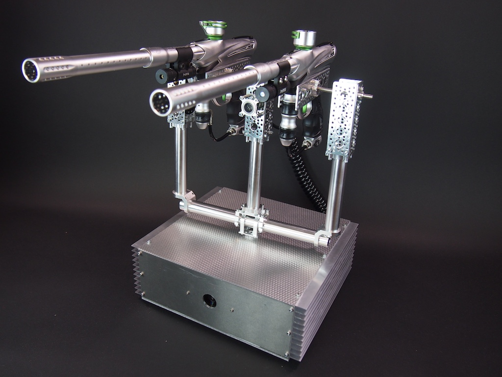
The Centurion is an automatic-targeting paintball sentry gun. Its purpose is to guard a doorway, alleyway, or any open space. It watches an area with its camera. If it sees movement, it aims its guns at it and shoots at a high rate of fire until the target leaves the field of view or stops moving. As long as the target keeps moving, the guns track the movement and keep shooting. It can also differentiate color. So, for example, team members with blue sweat shirts could be allowed to pass, but enemies with red sweatshirts will be dealt with severely. The main components are:
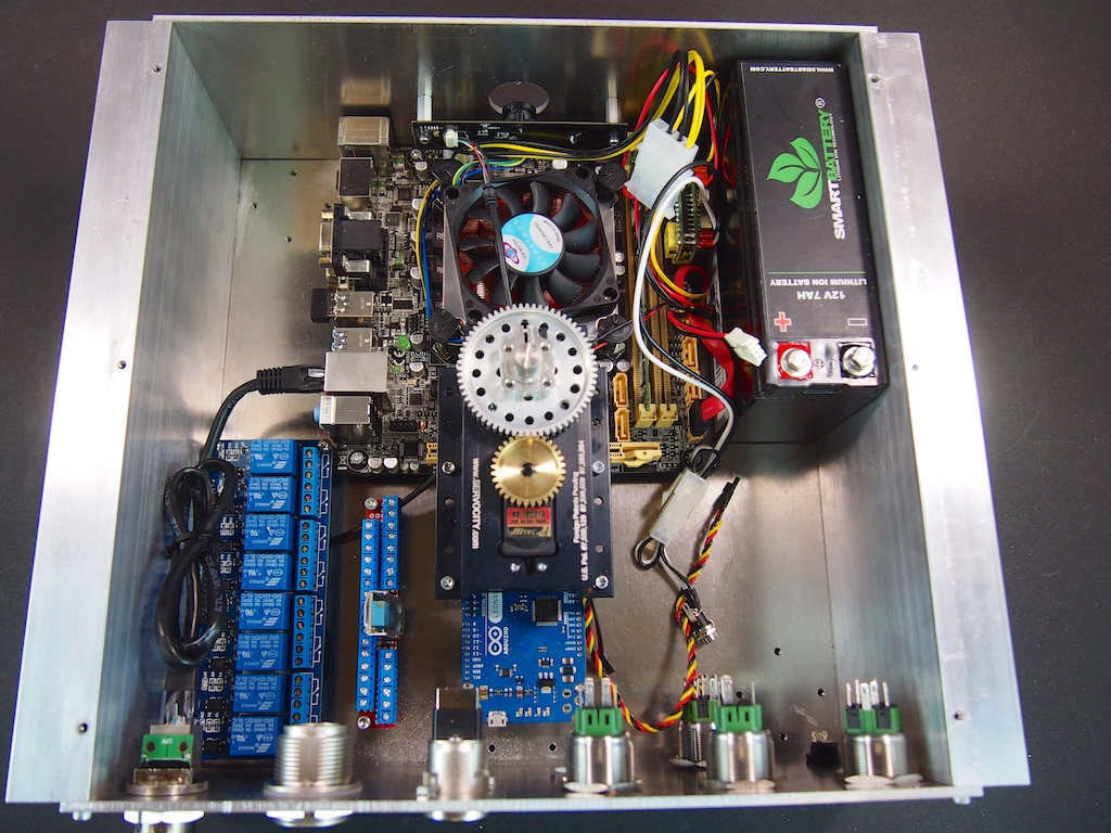
Motherboard with a Corei5-4570S Quad Core 2.9Ghz, 8GB RAM, 120GB SSD, & WiFi module
Arduino Leonardo
Wide-angle HD webcam
8-Channel Relay Board
12v 7,000mAh Lithium-Ion battery
Actobotics Pan-Tilt Turret
Actobotics tubes, channel, brackets, clamps, shafts, ball bearings, gears, and other components
Actobotics Hitec Servos
Maxbotix ultrasonic range finder
(2) high-performance paintball guns (Dye Proto Reflex 14’s with custom modified barrels)
(2) targeting lasers
(2) electric ammunition hoppers (not shown)
(2) air tanks (not shown)
Portable keyboard, mouse, and keyboard (not shown)(not necessary for operation)
We started out with the code from the open source Project Sentry Gun, which is written in Processing, and then went from there.
The Centurion is one of several projects that we work on just for fun when we aren’t working other projects. The whole system isn’t done yet, but we’ve made good progress on it. We are currently working on two new projects for the New York Hall of Science, so we won’t be getting back to this one for a while, but we thought we would share our work-in-progress.
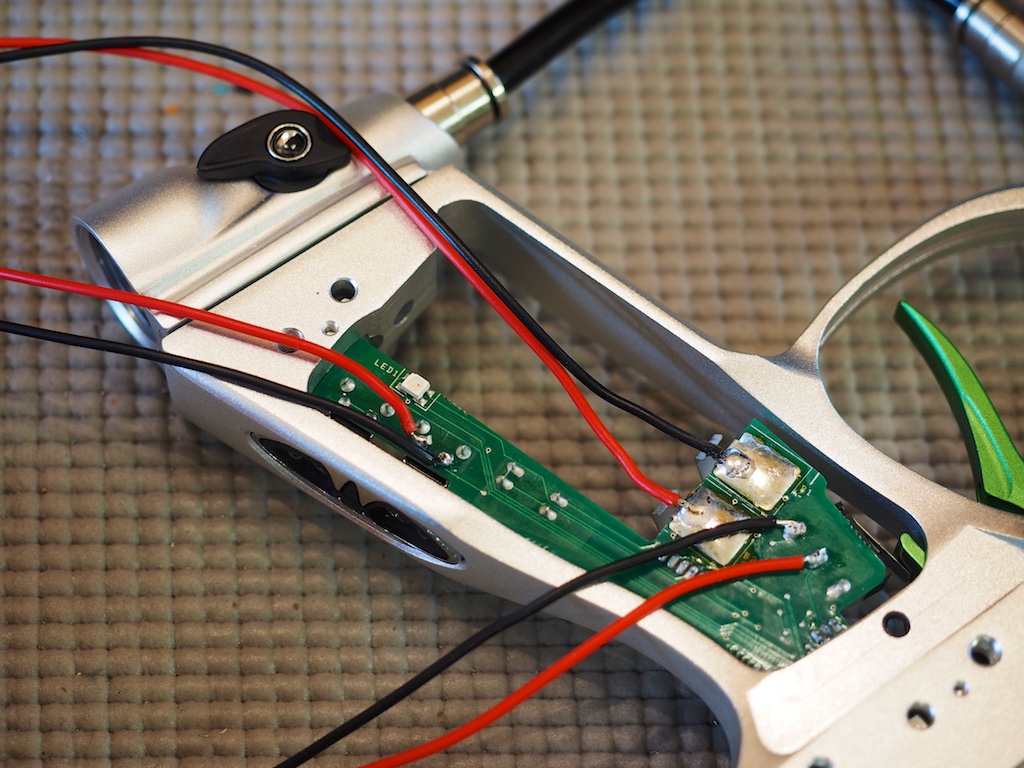
We hacked into the circuit board of the paintball guns in order to load and fire the guns electronically.
We reverse engineered the gun’s circuit board to figure out where we needed to hack into it in order to control the firing sequence.
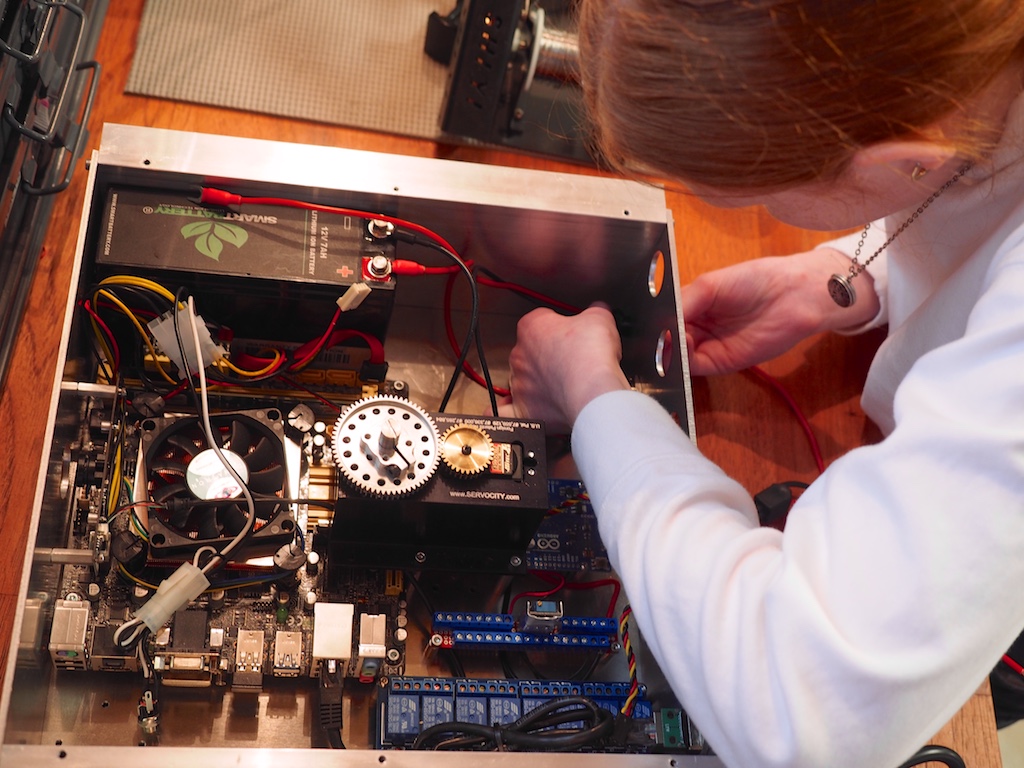
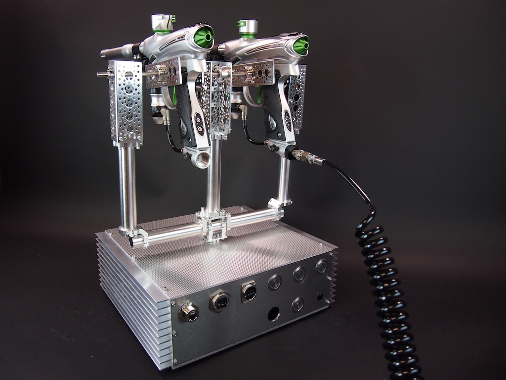
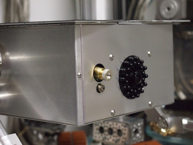
We built an aluminum enclosure for the electronics and the base of the pan-tilt turret, which is made with Actobotics hardware and servos:
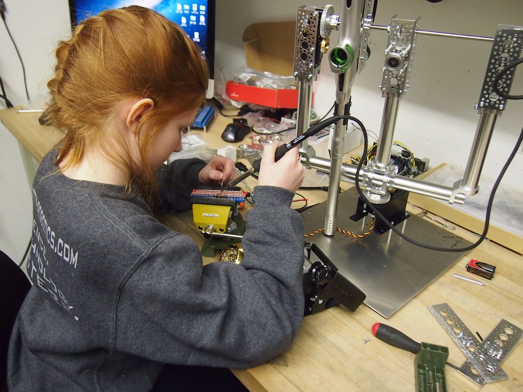
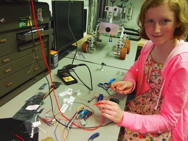
Genevieve wiring up the relay board, which will control the firing of the paintball guns. Is that a gentle smile or a devilish grin? Is she thinking about paint balls flying at anyone in particular?
Genevieve soldering the power distribution board.
Genevieve wiring up the control switches and buttons on the back of the electronics enclosure.
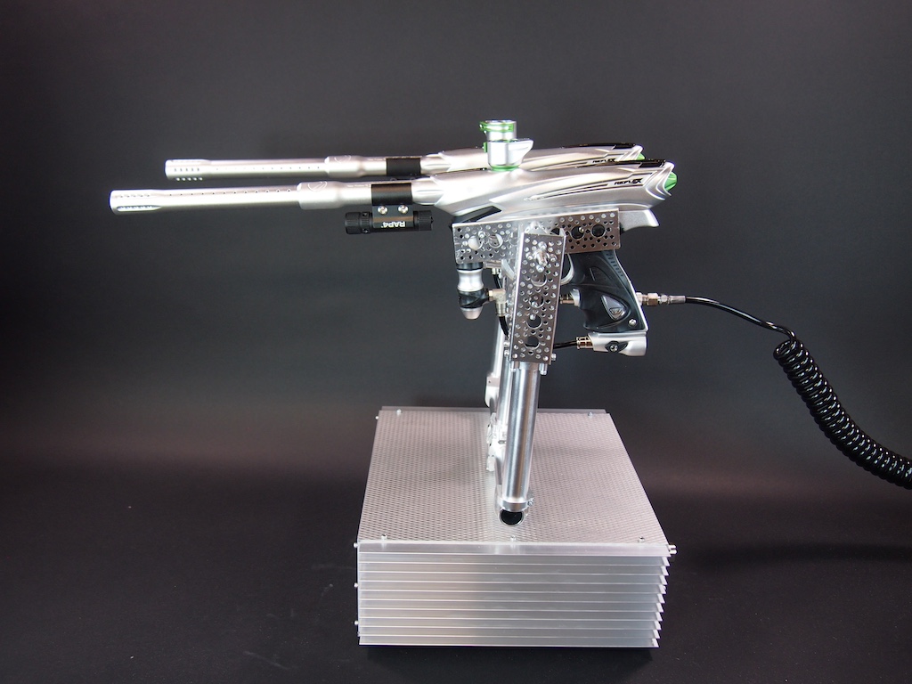
Back view of the Centurion Sentry Gun, including multiple jacks and push buttons:
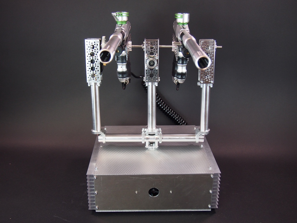
Front View, including the front port that the camera looks out of. When we are done, the port will be covered in glass.
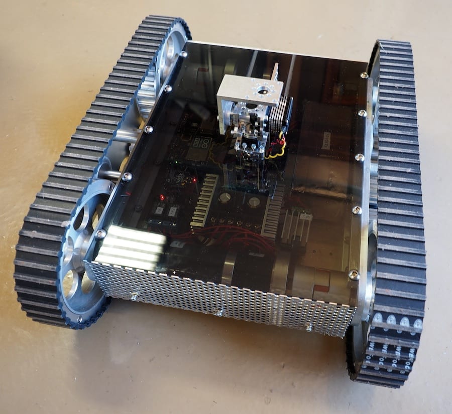
We are working on a tank with treads and a laser cannon gun turret. It’s a complex, long-term project with lots of CNC-machined parts as well a a variety of purchased components, but we’ve been making good progress on it. Today’s posting will focus on the base, which holds the electronics, provides mobility, and establishes a sturdy platform for the gun turret (not shown here).
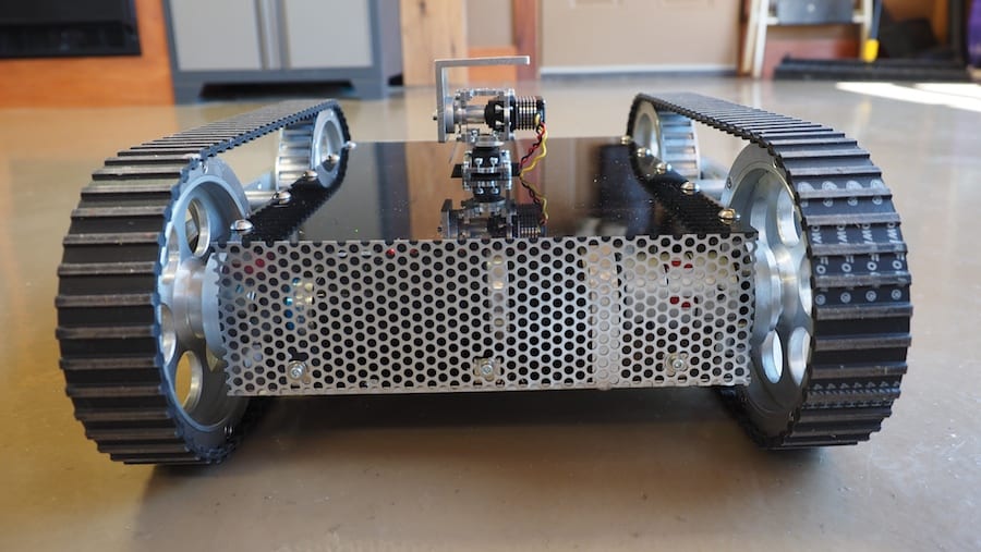
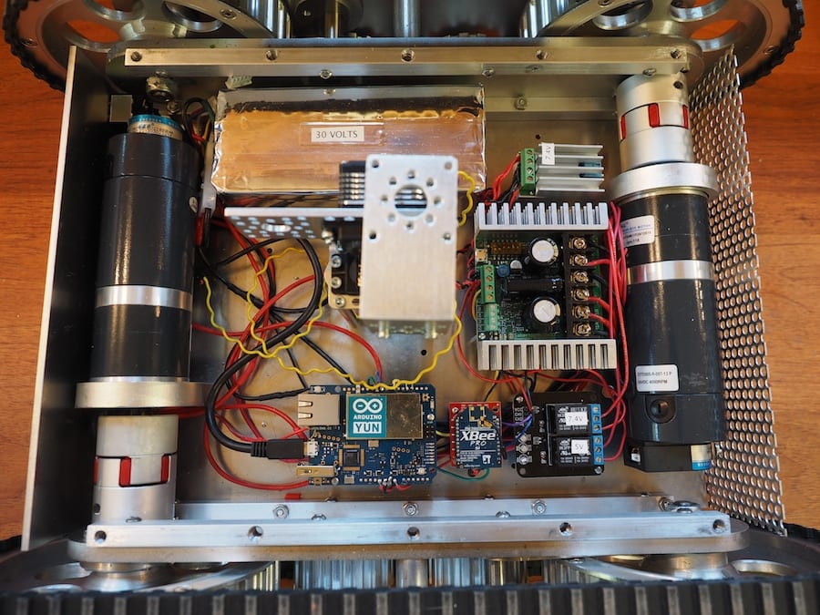
The robot is powered by a large 8-cell 30 Volt LIPO battery, our first ever. So we’ve got lots of power for the motors and the laser cannon. We are driving the wheels (which are actually timing wheels) with two beefy gear motors and a Sabertooth dual 32-Amp Motor Controller. The treads are timing belts. There are two machined aluminum plates (separated by standoffs) on each side that provide the mounting for the wheels. We are using an Arduino Yun for the first time in this robot, which is a new microcontroller that integrates Linux and Arduino into a single board, which among other things, provides for a nice wifi layer, including WiFi-based software updates. We’re using an AnyVolt voltage regulator to bring some of the 30V down to 7.4V for the gun turret servos and the laser cannon. And we have a second voltage regulator for the 5 volt components. The Arduino will trigger relays (shown) to turn on the four targeting lasers and the main laser cannon (not shown), which will laser-burn targets using an autonomous targeting system. This photo also shows the four multi-tapped rails that we made to hold the robot together, including the track sub-assemblies on each side, the bottom plate, and top plate. The front plate and rear plate are held onto the bottom plate with six small #6-32 angle brackets. To better visualize the scale of this robot, the bottom plate is about 10″ wide and 13″ long.
The CNC-machined back plate includes the main power switch, a USB jack for programming (although we’ve been using the Yun Wifi for that), banana plugs for charging, and a fuse.
There are many things we like about this robot so far, but we were especially pleased with the smoke-gray acrylic top that we machined on our CNC. It’s transparent enough to see the circuit board lights on the electronics, but opaque enough to give it a nice blackish sheen. The main top plate is held onto the rails with a bolt pattern of ten 1/4-20 bolts. The difficulty with gun turrets is that you can’t get the top plate off the base without removing the gun turret, which is a pain, so we machined a slot into the main top plate. We didn’t want to use fasteners or a hinge on the acrylic, so we machined mating shelves (grayish area along the edge) so that the small back plate press fits perfectly into the top plate and stays there without needing any fasteners.
A few subscribers have asked about laser and the thermal array sensor on the new Mars Rover, so this post is dedicated to that:
We needed to add a targeting laser and a thermal array sensor to the Mars Rover robot, so we experimented with different wavelengths of lasers and types of lenses. After looking at the results of our tests, we decided on a 532 nanometer laser (which is bright green in color), with adjustable 5 to 25 milliwatts of power, and a 38-degree line-generating lens.
We plan to use a TPA81 Thermopile Array sensor to scan the temperature of the objects that are out in front of the robot (a few feet or a few yards away). This particular sensor provides an 8 x 1 array of eight temperatures corresponding to eight points from left to right in front of it (about 40 degrees across). But it’s hard to tell exactly where it’s pointing and which objects it’s measuring, so we plan to use the laser to identify the scanning zone. We cobbled together a prototype and our initial tests of all this worked well, so we moved into the final build stage and mounted it into the robot. The key was to make sure that the laser was lined up with the thermal array sensor, which necessitated a special mounting mechanism.
Here I am with a devilish grin as I experiment with different types of lasers. I decided on the green laser because it’s strongest, easiest to see, and “just plain the coolest.”
I used my favorite tool, the vertical mini mill, to do some machining to modify the laser mount. We then drilled and tapped various threaded holes into the mount.
Here is the finished Laser Mount. The laser fits in the large hole in the middle and is held with a set screw through the threaded hole on the side. The threaded hole on the bottom is used to attach the mount to the articulating arm. The threaded hole on the face (top in the picture) of the mount is used to attached the Thermal Array Sensor. This way the Laser and Thermal Array Sensor are screwed together and always pointing in the same direction/angle.
Here we have mounted the Target Laser (on top) and the Thermal Array Sensor (on the bottom) into the front of the robot (front plate removed). You can’t see it too clearly in this picture, but the laser mount sub-assembly is mounted on an articulating arm on a base so that we can adjust the pointing angle/direction. Please note that the line generating lens is tilted in this picture and needs to be adjusted so that the visible lines in the lens are vertical (which is weird because it generates a horizontal line).
The finished result. We’re ready to scan some alien Martian life ! (Or at least some warm rocks!) 🙂
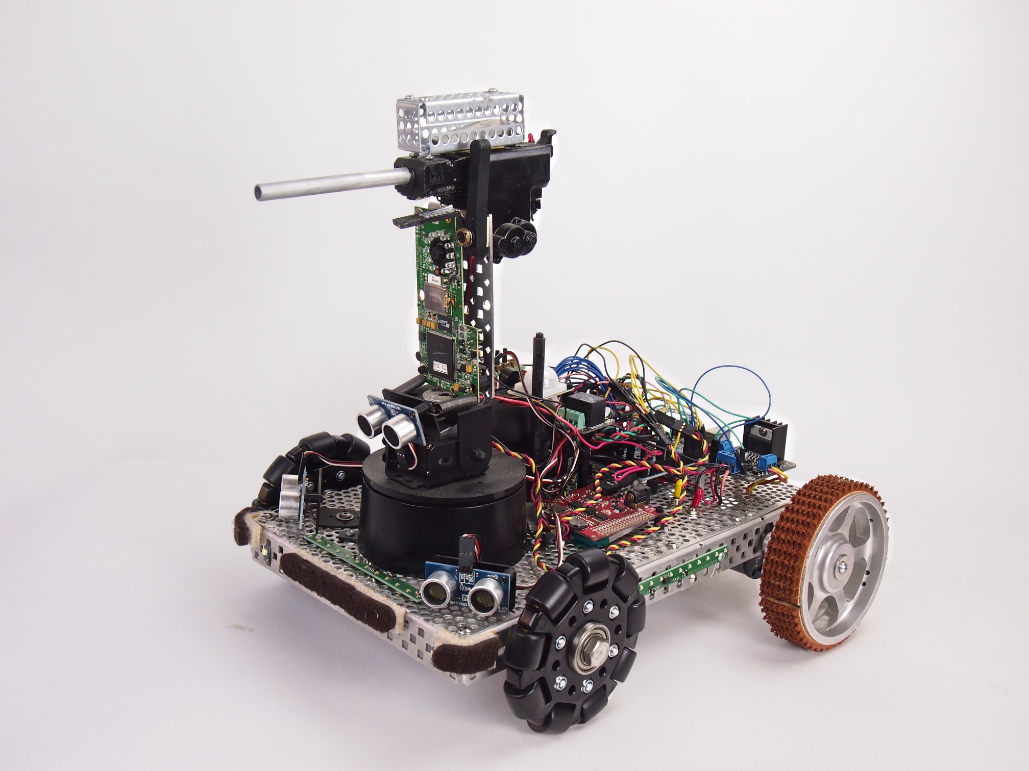
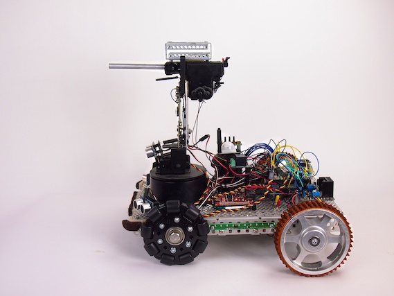
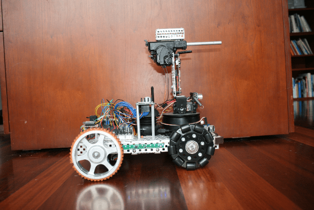
Security V is a small security robot. It’s equipped with the following capabilities:
Automatic electric gun (Airsoft pellet gun) with ammunition cage
Pan-Tilt Gun Turret
Targeting laser
FPV Camera
(3) Ping sensors for object avoidance
LED Light Strips
MP3 Sound Player
IR Human Detection Sensor
Moto Controller
Two motors
Two treaded drive wheels and two omni wheels
Arduino Mega Microcontroller
Xbee Radio for remote control
Button panel for selecting the mode
We programmed it with five different modes:
1. Roams autonomously around the house, playing R2-D2 like sounds as it explores & avoids obstacles 2. Remote Control 3. Dance Mode (Plays the song Mr. Roboto and dances around) 4. Guard Mode (enables its infrared human detection sensor and plays a police siren if anyone tries to sneak past it) 5. Shoot (shoots the gun)
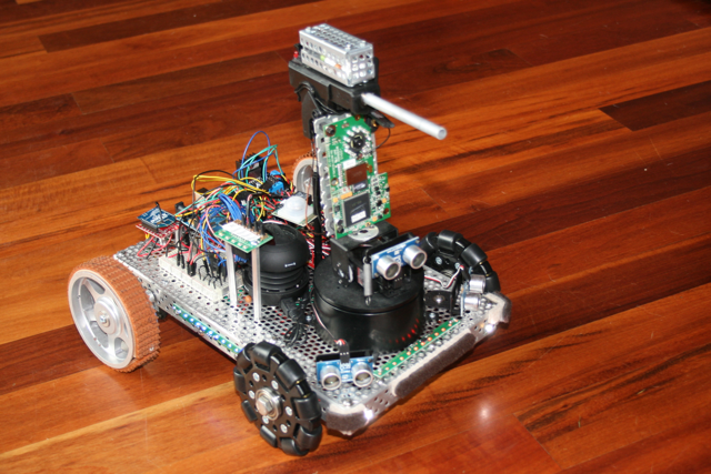
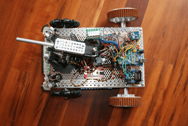
Security RobotSecurity RobotSecurity Robot – Top View