by Camille | Robots, Slider, Workshop Blog
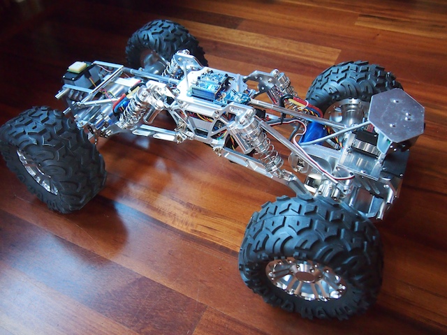
Today, we would like to introduce Terrabot, our Terrain Traveling Robot. Based on a modified “rock crawler” chassis, its primary purpose is to traverse rocks, branches, steep slopes, flower beds, boulders, mountain trails, and other extremely rough terrain.
Terrabot

Terrabot is equipped with 4-wheel steering (4WS). Two high torque servos shift machined aluminum linkages to rotate its front and back wheels independently. Note the navigation GPS on top of the back servo (on the left) and the sensor turret on the front (right). Terrabot’s four wheels are driven by two powerful brushless motors (bright blue) and robust gearboxes (centered in each axle).

Terrabot’s highly-articulated chassis is designed to twist up to 90 degrees as the robot is moving, allowing it to climb over huge boulders and other obstacles. In this picture, the chassis is articulated 45 degrees. Note that the back tires are still on the ground because the center linkages of the bot are twisted.

Terrabot’s topside electronics include a tiny Arduino Nano (lower left), an XBee Radio (right), and a 9-DOF Mongoose Inerntial Measurement Unit (IMU). The IMU measures the degree of tilt and the rate of acceleration in the X, Y, Z planes, which we plan to use for our stabilization algorithm.

Terrabot’s other electronics are stuffed into the little chamber inside the aluminum core (note the blue LED at the bottom of the picture). This includes the two Electronic Speed Controllers for the motors, the Pololu Maeastro motor/servo controller, the power rails, various voltage regulators, and other electronics. The navigation GPS (see the first picture), is mounted on top of the rear servo so that it has a clear view of the sky.

Terrabot Side View, showing the shocks, the frame, and LIPO battery beneath. Note the “roll posts” we installed on the top to protect the topside electronics if Terrabot falls off a rock during a climb and flips over. (We learned this one from experience!)

Terrabot Front View. There are three sonars mounted in the sensor turret, which rotates 270 degrees when the robot “looks around” to determine the best course through obstacle-ridden rough terrain.
by Camille | Robots, Slider, Workshop Blog
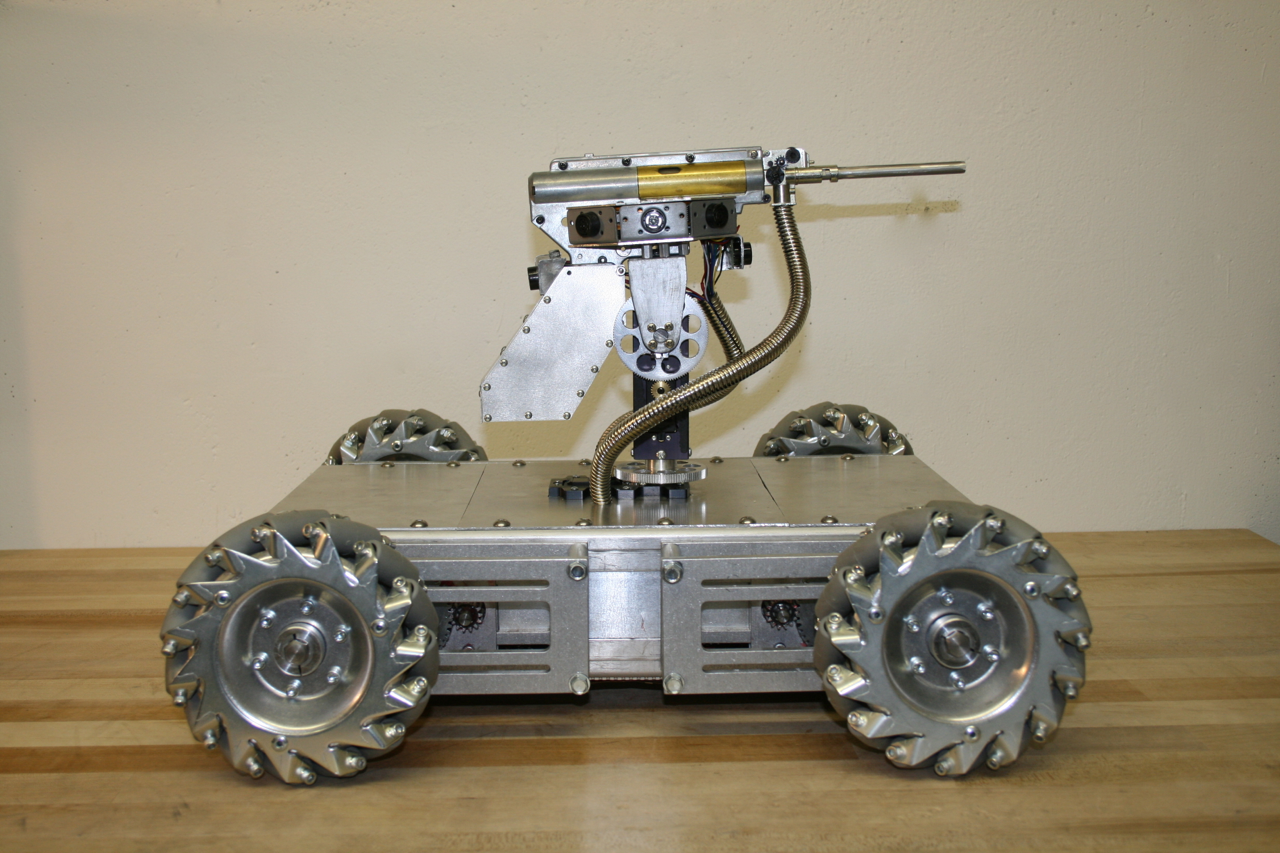
We would like to introduce Mechatron, our mechatronic tank. When we designed and built Mechatron we wanted him to be tough looking, industrial, and retro-futuristic, with lots of metal, rivets, and gears. He’s built entirely out of aluminum, brass, and steel, but inside, he’s chock-full of high tech electronics. See pictures and more text below. And be sure to watch the video to see Mechatron in action!

Mechatron includes special wheels with rollers slanted at 45 degree angles and driven by dedicated gearboxes, four powerful motors, and a software-controlled drive system that we wrote that operates each of the wheels independently. The result is that he can move in any direction at any time in any orientation. In other words, he can drive forward and backwards or turn like a normal vehicle, but he can also drive perpendicular to the direction he’s facing or at any desired angle. Weighing in at forty five pounds, he is by far our heaviest robot, but he is also our most agile, which makes him tremendous fun to drive.
Mechatron’s gun turret pans 360 degrees, includes 8 range-finding sonars for target detection, a laser, and a high-powered electric automatic weapon that shoots brass or plastic pellets. Ammunition is fed from the base of the robot up through one of the articulated metal tubes attached to the turret (the other tube contains wires). He can fire extremely rapidly while standing still or moving.
Strips of 52 programmable RGB LED lights have been mounted on Mechatron’s underside and within his turret. The turret LEDs indicate the robot’s current mode and whether the weapon system is armed. The LEDs on the underside change color depending on the direction of each of the individual wheels (Blue = Stopped. Green = Forward. Red = Backward), which helps to illuminate how Mechatron’s unique drive system works.
Mechatron is designed to function in a variety of different modes, including both user-controlled Radio Control and/or fully-autonomous. For the RC mode, we built our own controller which matches Mechatron in look-and-feel. The left joystick controls the pan and tilt of the gun turret and includes the firing button on top (which is armed using the missile switch). The right joystick controls the drive system. Forward and Backward motion (Y-axis) moves the robot forward or backward. Twisting the joystick turns the robot in the direction of twist (Z-axis). Moving the joystick left or right (X-axis) causes the robot to strafe left or right while maintaining his current orientation. Combined X-Y-Z joystick motions create unique and agile movements, such as strafing in circles. The robot can move in any direction, while panning and tilting its turret and firing all at the same time.
Technical Specifics:
- Overall Design: Beatty Robotics
- Arduino Software: Beatty Robotics
- Metal armor plates: Beatty Robotics
- Main Microcontroller: Arduino Mega 2560
- Microcontroller used for controlling LED lights: Arduino Nano
- Light Controller Software: Beatty Robotics
- Wheels: AndyMark (special thanks to Andy Baker, who was great to work with on these)
- Drive Gears: Modulox (special thanks to Dan Richardson at iR3 Creative Engineering & Andy Baker at AndyMark)
- Pan-Tilt gears and other parts: RobotZone (special thanks to ServoCity)
- Pan-Tilt Servos: Hitec Digital
- Sonars: (12) Maxbotix MaxSonar Ultrasonic Sensors
- Turret Sensor Head: Beatty Robotics
- RGB LED strips: Adafruit (Go Blinky Belt!)
- MP3 Sound Board: Sparkfun MP3 Trigger
- Servo Controller: Pololu Maestro
- Voltage Regulators: Pololu & Dimension Engineering
- High-amp Relays: DFRobot
- Motor Controllers: (2) Dimension Engineering Sabertooth 2×25
- Motors: (4) CIM
- Wireless Communication: Xbee Radio with Sparkfun Xbee Explorer Regulated board
- Joy Sticks: (2) 3-axis hall-effect joysticks from CH Products
- Batteries: (1) 12v 3-cell Lithium-Polymer 20C
- Aluminum, hardware, fasteners, wire, tools, and much else: McMaster-Carr
- Wire, electronic components, IC boards, and much else: Sparkfun & RobotShop
by Camille | Workshop Blog
We are currently building a rover similar to the Mars Rovers Spirit and Opportunity, which we have always loved (but have been way outside our skillset in the past).
We have been studying the details of the rovers, their electrical systems, chassis, wheels, and so on. Ours won’t be exact, of course, but hopefully, if all goes well, it will be a nice working model, including the solar panels.
One of the most unusual and characteristic elements of the Mars Rover design is what they call a rocker-bogie suspension system (http://en.wikipedia.org/wiki/Rocker-bogie), which is intended to help the rover go over rocks. This system involves six wheels, with a special interconnection between the various wheels so that at least one or two of the wheels on each side are on the ground at any one time, even when going over obstacles. It took a while to figure it out, but this design requires a connection between the wheels and each side such that when the wheels on one side go up over a rock the wheels on the other side go down and vice versa. NASA uses what they call a “differential” (although it’s not the same as a car differential).
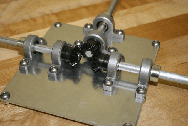
Anyway, we couldn’t find a counter rotating differential that met the requirements, so we decided to make made one. We’ve attached a picture. The plate, pillow blocks, and shafts are made out of aluminum. There are three bevel gears, which are made out of steel. This gear box will go inside the center of the robot’s main box directly between the wheel sets on each side. The way we’ve meshed the gears together creates a counter rotating shaft so that when one side goes up the other side goes down.

Counter Rotating Differential for Mars Rover

From Above

Close up of bevel gears

