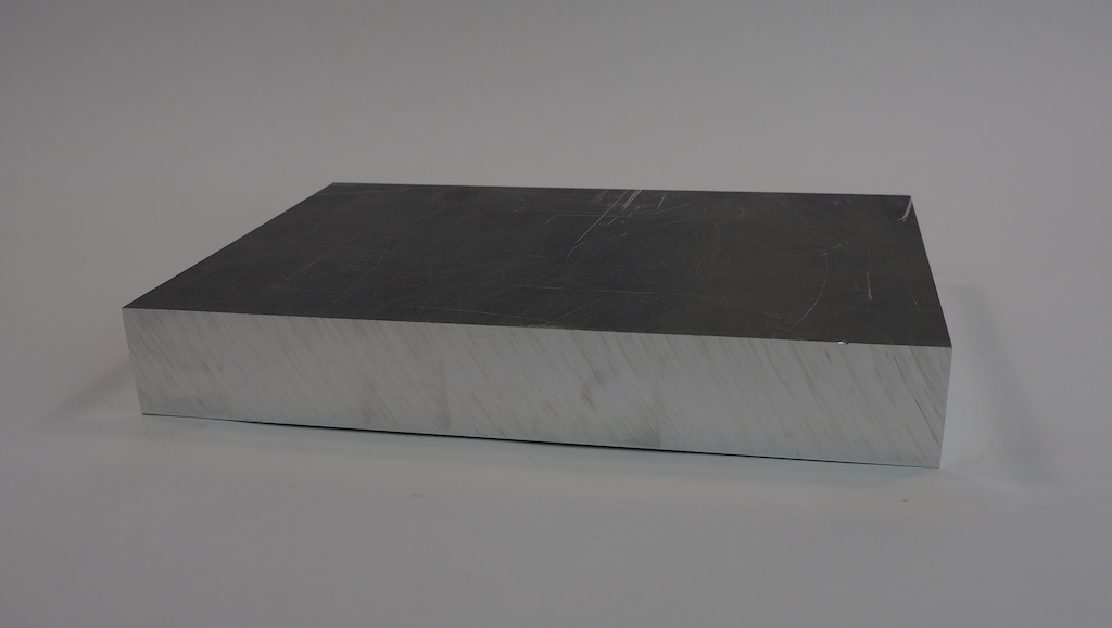
We’ve been working on a fun new robot we call Metalbot. Our goal was to build an autonomous rover with a unibody design that was machined out of a single block of metal. We started with this 13” x 9” x 1.75” block of 6061 aluminum:
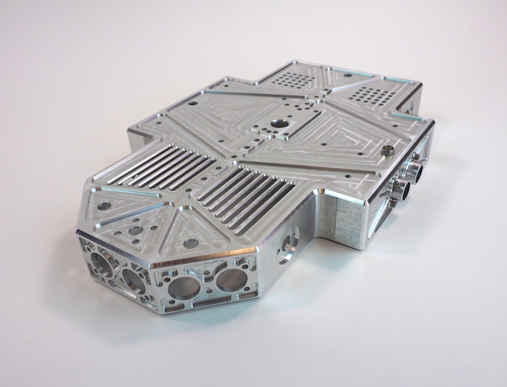
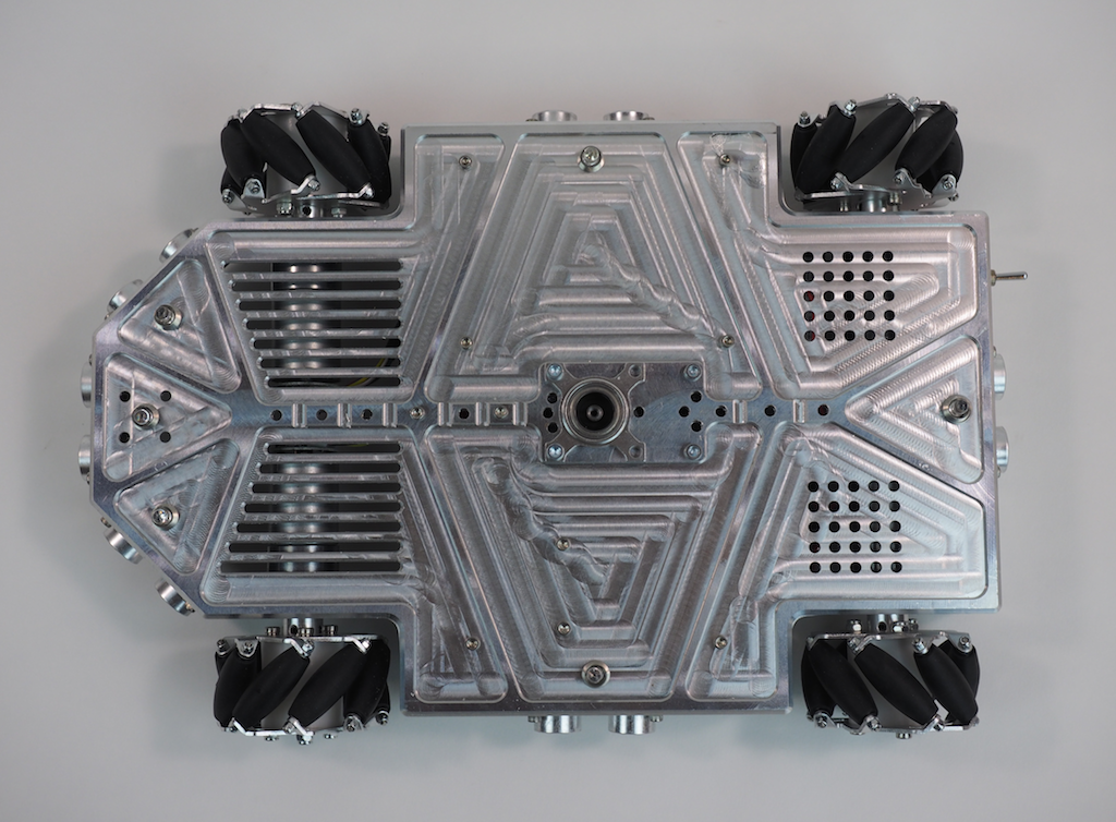
When the machining was done, the robot’s body looked like this. It’s a hollowed-out shell that is about 1/8” thick with holes, slots, and pockets for the motors, LEDs, sensors, and other electronics.
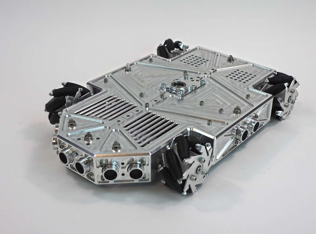
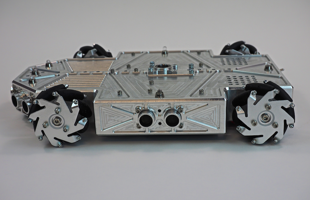
Once Metalbot was assembled with the internal components, it looked like this:
What do you think? We think it’s pretty cool looking. Do you like it?
Work-in-Process Pics
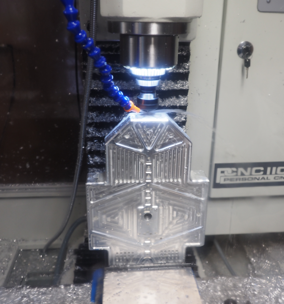
In this first picture (which was taken through the polycarbonate enclosure), we clamped the part vertically in the vise and we’re using an 1/8″ end mill to machine the detail on the front of the nose. In a previous operation we clamped the stock flat and machined the top of the robot, so that work is already done. Because this part has features on every side, machining it required us to clamp the stock in the vise in 8 different orientations: top, left side, right side, back, front, 45-degree left nose, 45-degree right nose, and bottom.
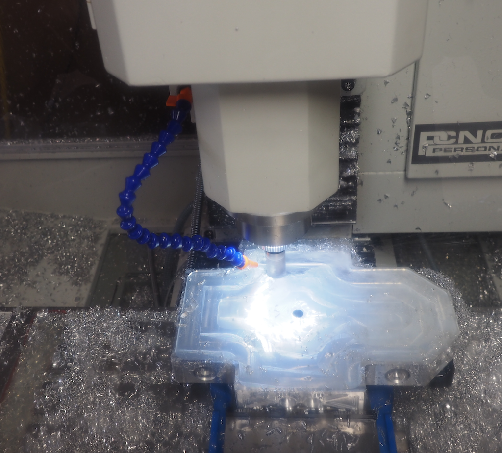
In this next picture, we’re on the last setup, machining out the large pocket on the underside of the robot. This turned the aluminum block into a 1/8” thick shell. The large pocket appears to be glowing because the ring of LEDs we installed around the mill’s spindle are shining into the coolant that has filled the pocket. We’re using a 25mm (.98”) modular end mill here, which is designed to remove material fast. Of course, there were a lot of metal chips, but it’s important to remember that aluminum is easy and efficient to recycle.
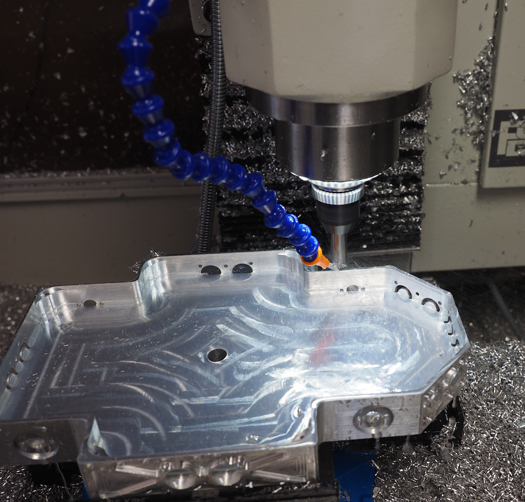
In this picture we’re half way done digging the pocket and we have the machine take a break from the hard work to chamfer the outside contour:
Once the body is machined, we screwed in the wheels, motors, and electronics, which are screwed upside down on the underside, where they are easy to access when the robot is turned over. We will install a bottom plate later.
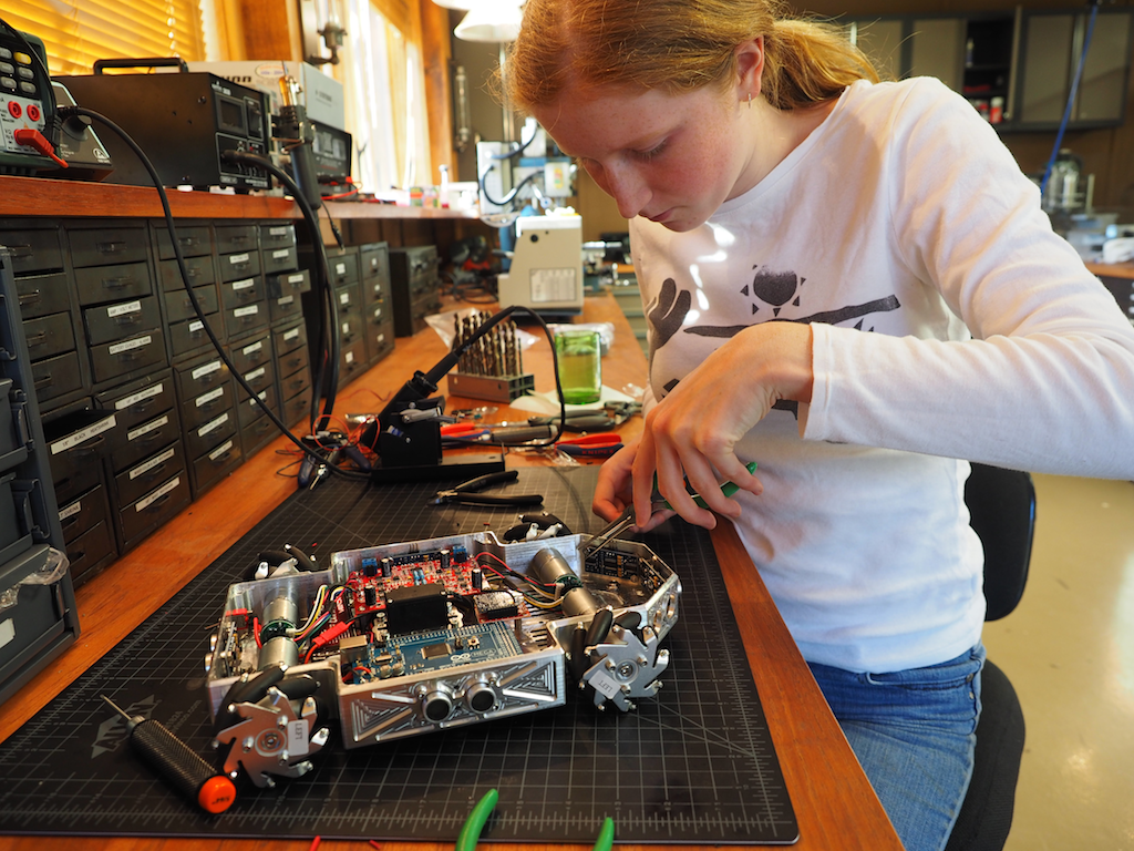
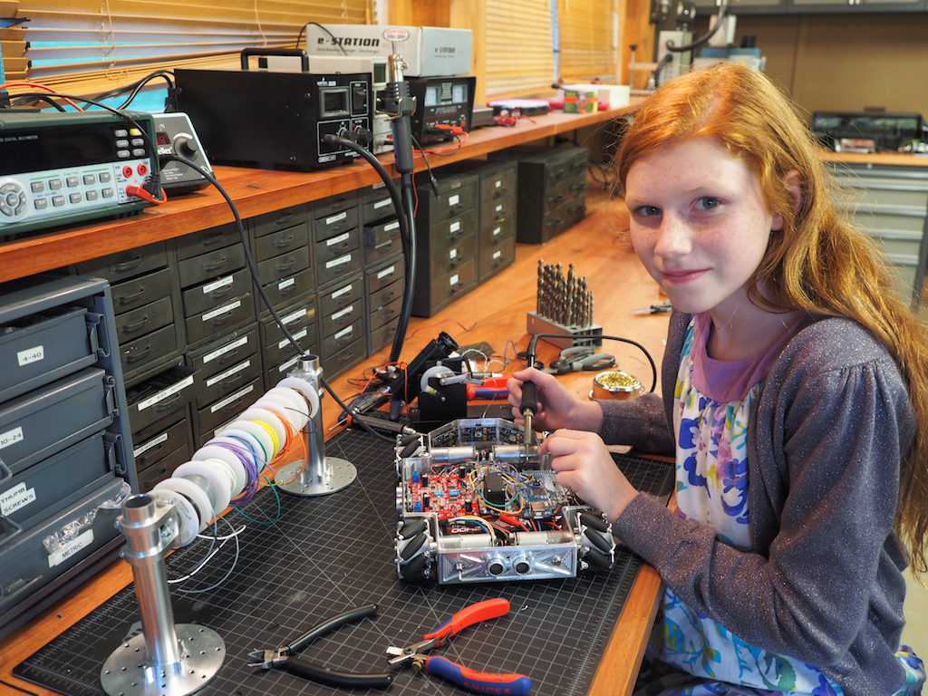
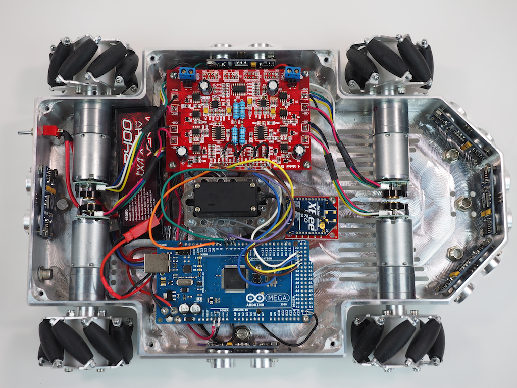
Then we did the wiring and soldering:
Here is the underside of the robot with most of the electronics installed. We’re using an Arduino Mega and a 4-channel Motor Controller, along with 4 Pololu gear motors to drive the mecanum wheels, which will allow the robot to strafe. The robot is also equipped with 6 Ping ultrasonic sensors for autonomous object detection, a LIPO battery, a main power switch, 6 NeoPixel RGB LEDs to indicate the state of each sensor, an Xbee Radio, and a panning servo (black thing in the middle). The robot will also be equipped with an MP3 module and speaker for sound, but those haven’t been installed yet.
The robot’s finished body is 8” wide and 12” long. The rover can be fitted with either the mecanum wheels shown or CNC-machined conventional wheels (not shown). Our original goal was just to machine a cool looking rover out of a single piece of metal, but as we went along, we decided to add some flexibility into the design for future enhancements in case we wanted to do more with it. The robot has been designed with a central spine of holes and ridges for attaching future add-ons, including a servo mounted in the center, which will support a pan-tilt turret for a camera, gun, or arm. We have designed the pan-tilt turret to utilize the Actobotics ecosystem, but other pan-tilt mechanisms could also be used. There are also holes on the front and rear of the top deck that are compatible with the full range of Actobotics components such as brackets, hubs, and channels, which really adds a lot of flexibility.
The next step is to work on the sensors and software programming. With its mecanum wheels, it should be able strafe like a champ very soon.
Here are a few more pictures of Metalbot so far. Let us know what you think. Do you like the overall design?
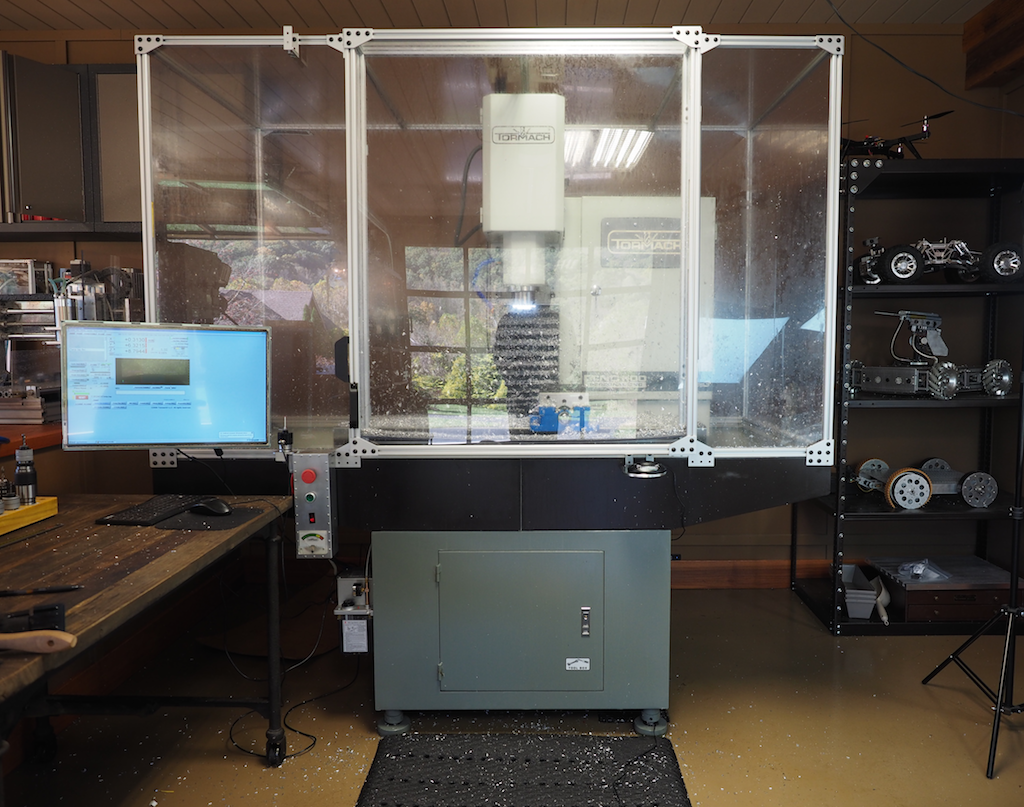
At Beatty Robotics, we’ve made good use of our gantry-style CNC mill over the last few years. We’ve built all our robots to date with it. Recently we decided to augment our machining capability with a vertical CNC mill. Our current mill has been excellent for machining large flat parts out of sheet aluminum, but now we wanted to be able to machine parts that were deeper and more three dimensional, as well as use coolant and a greater variety of tools. After extensive research of all the various machines available, we decided on a Tormach 1100. We bought and installed the base Tormach machine, then extended it with various add-on kits and our own customizations to turn it into a lean, mean milling machine. We’ve only had the mill for about a month, but we love it so far. The Tormach’s capabilities, features, and price are geared toward professional machinists, small businesses, and prototype shops, so the Tormach isn’t affordable for most hobbyists, but it is an excellent machine. In future posts, we’ll show you some of the parts we’ve made, but for now, here are some details on our installation.
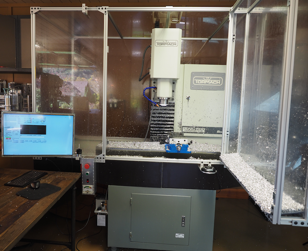
The base machine weighs 1130 pounds, so in addition to the mill itself, we purchased Tormach’s stand kit to make sure we supported the machine properly. The chip tray’s bright white color didn’t fit too well in our shop, so we painted it oil rubbed bronze (in case you were wondering why it doesn’t look like other Tormachs you’ve seen). We then constructed a full enclosure of our own design using 80/20 and 1/4” polycarbonate plates. The enclosure keeps the flood coolant and chips contained, reduces shop noise, and improves safety. Part way through the building of the enclosure we ran out of the metal plates and brackets we needed. It was late on a Friday night and it stopped our project dead in its tracks. No problem. We jumped on the CAD system, designed the parts, and machined them on the mill. Very cool.
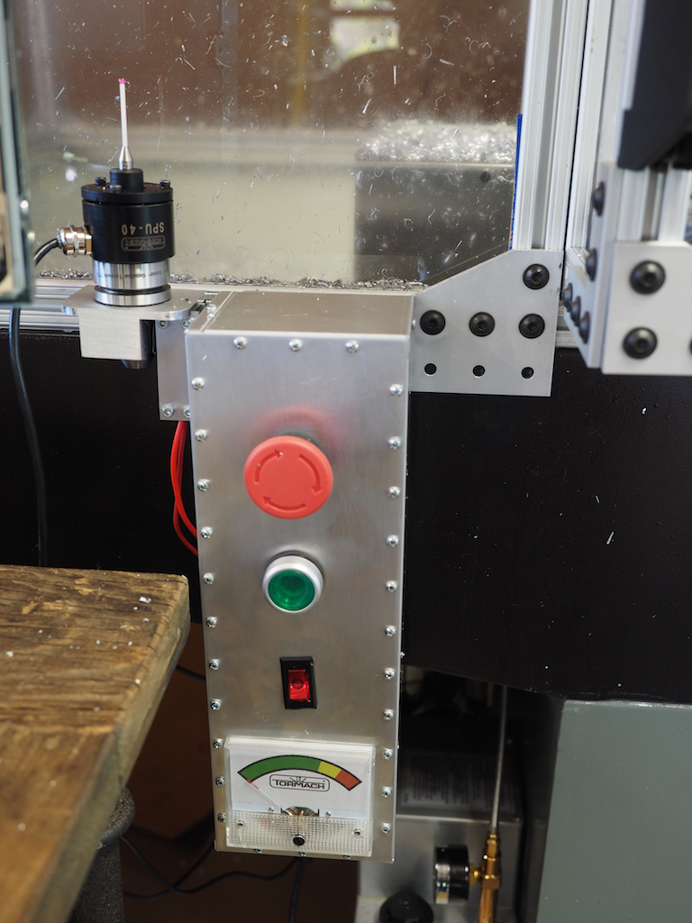
The control panel on a standard Tormach is located on the electrical box just to the right of the spindle, which put it inside the enclosure, so we rewired the electrical controls so that they were accessible from outside the enclosure. We also simplified the controls to just what we needed: Emergency Stop, Start, Computer Power Button, and Spindle Load Gauge. Everything else is controlled via the computer screen.
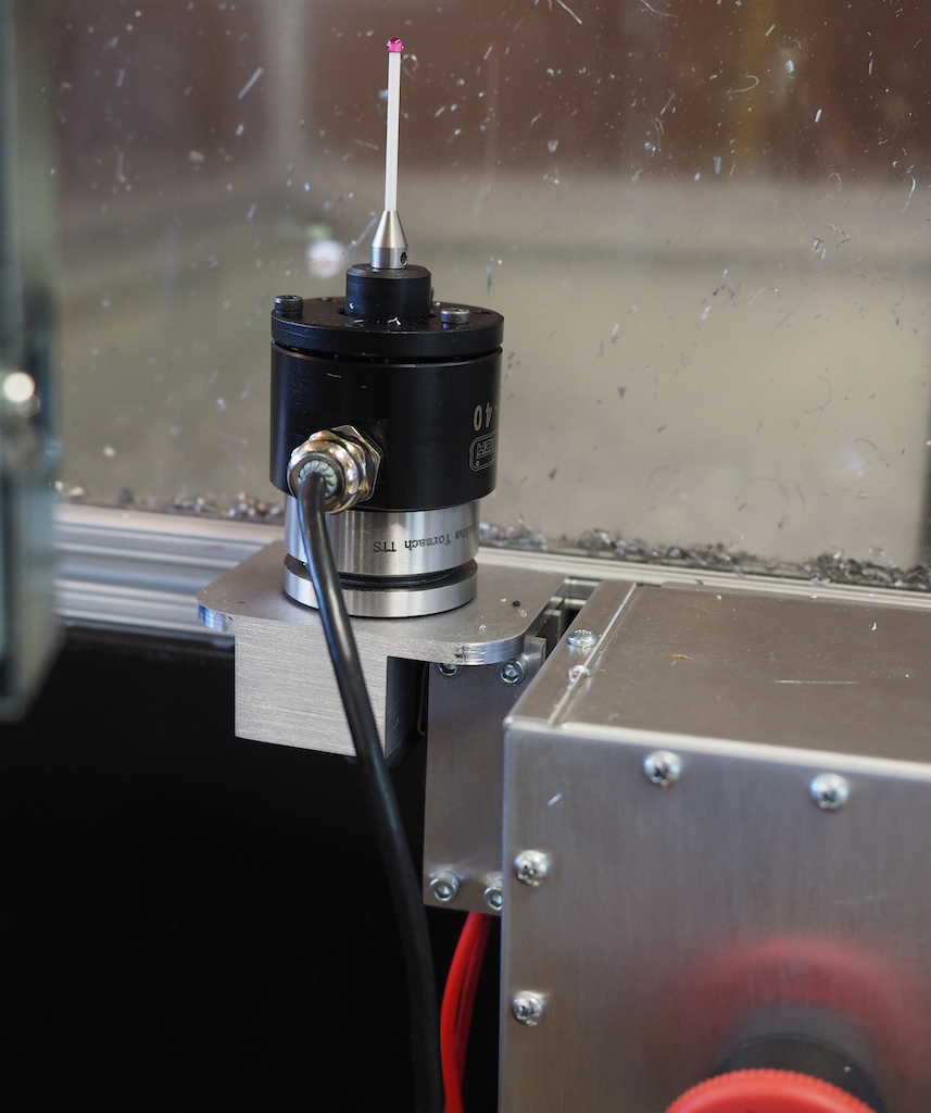
When we setup a part in the machine, we use an electronic touch probe, which allows us to find the X, Y, and Z position of the workpiece very precisely, which is critical to making good parts. We love using the probe, but the problem was that there is a bug in the Mach3 software’s probe wizard. In some cases, when you run the probe wizard, Mach3 turns on and spins the spindle, which yanks out the probe cable, whips it around at high speed, and destroys the probe. To make sure this never happened to us again, we wired the spindle power through a custom bracket we designed with a high-amp lever switch. When the probe is resting in the bracket, which is now its normal storage location, then the spindle will operate as usual. But when we pull the probe out and put it in the spindle for probing, the lever switch will cut power to the spindle so it can’t spin even if the buggy software tells it to. It was a really nice way to fool-proof and simplify the job setup procedure. [Important April 2015 UPDATE: Tormach now offers their new own, internally-developed Path Pilot software instead of Mach3. Path Pilot is a much better, more robust approach for running the Tormach. And best of all, this was a free upgrade to all previous Tormach owners!].
In the picture below, you can see the probe resting in the custom switch bracket we designed in SolidWorks and then machined on the Tormach.
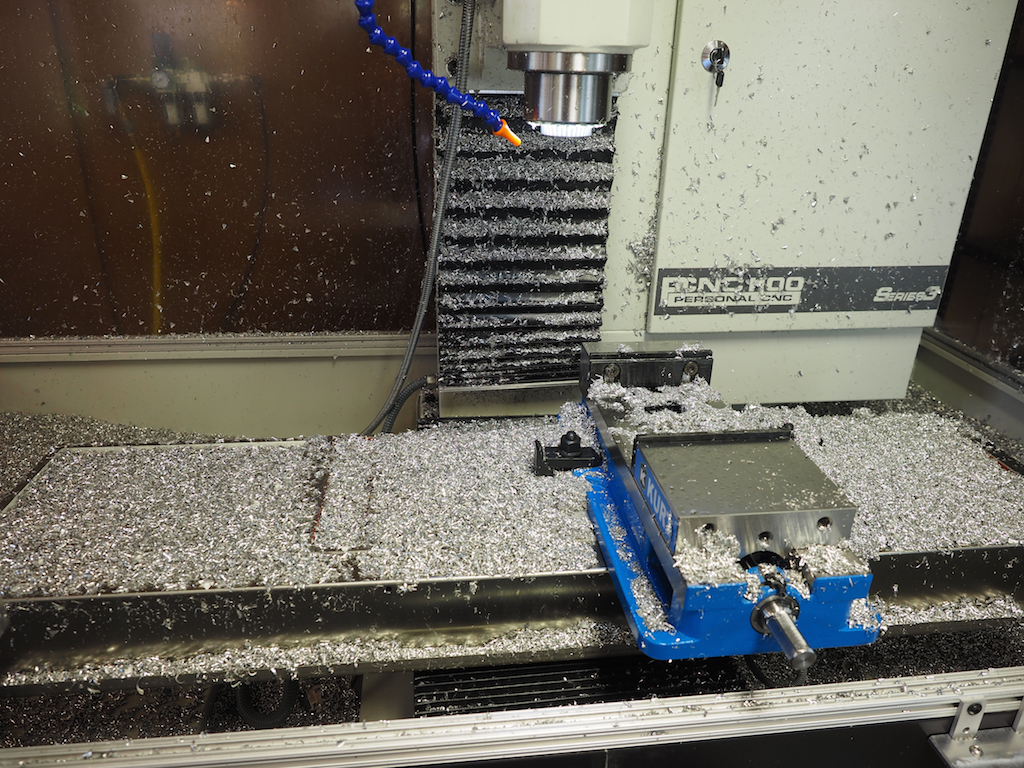
Clamping and fixturing is often the most time consuming and troublesome part of running a job, so we put significant time into figuring out the best approach for our particular situation. After studying all the different kinds of parts we plan to machine, we designed our fixturing system around a 6” Kurt Vise with quick-change SnapJaws. Our goal was to leave the vise in the machine for 95% of our jobs. One of the trickiest elements of building the enclosure was to make sure that the vise didn’t hit the enclosure wall during the machining operation. It’s hard to tell from the picture, but the large door on the front of the enclosure is actually extended out 5” from the rest of the enclosure in order to give the vise plenty of room when the table is moving. Here’s a picture of the Kurt vise mounted into place, where it was promptly buried beneath a mound of chips.
The mill with the enclosure door open.
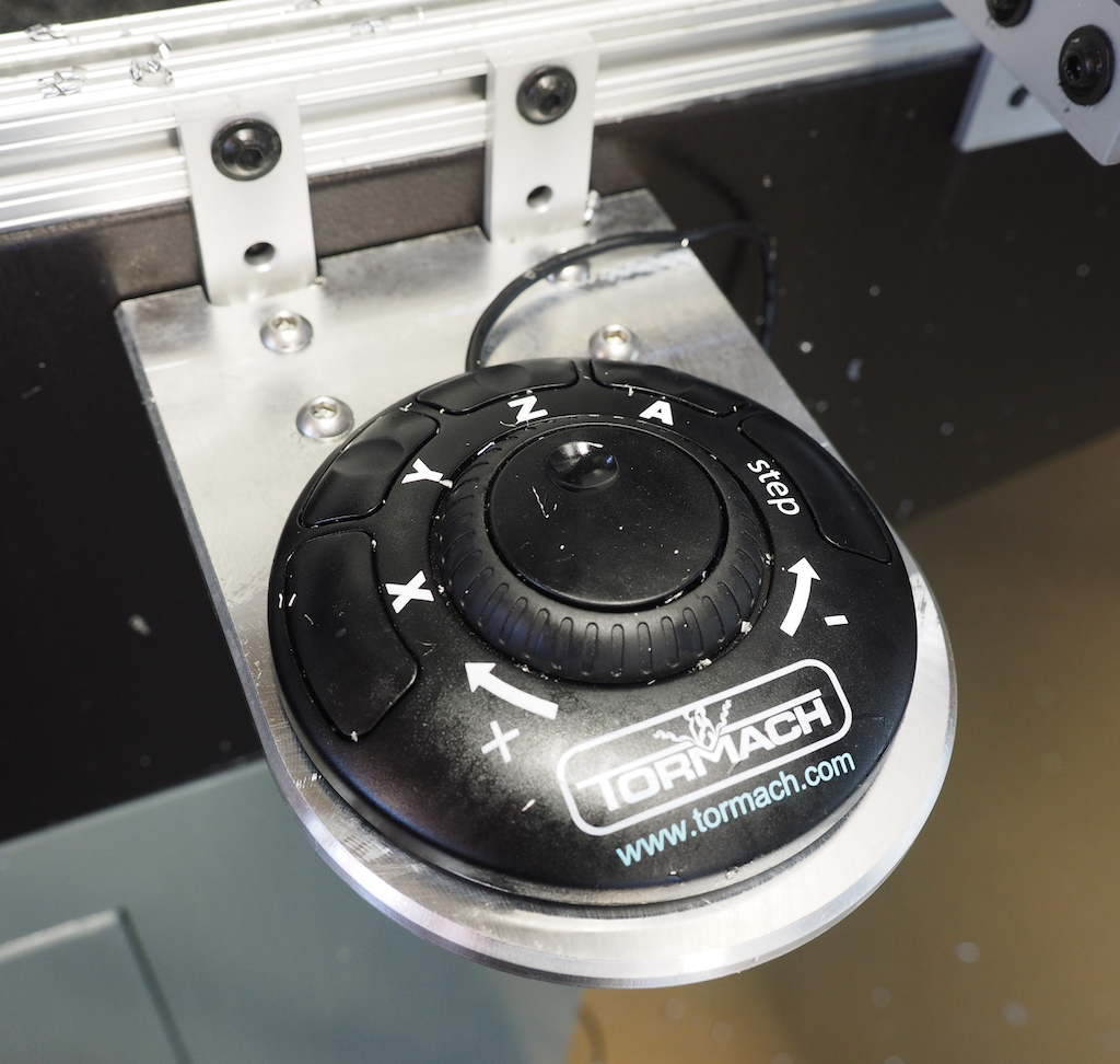
We also designed and machined a bracket shelf so that we could place the jog controller exactly where we wanted it, hovering on the right side just below the door so that we could use it whether the door was open or not.
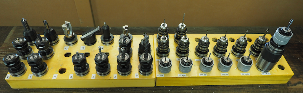
One of the best things about the Tormach is the Tormach Tooling System (TTS). It’s a well thought out approach to standardizing and simplifying tool heights so that mid-job tool changes are super fast and accurate. Here’s a picture of the tools and tool holders we have so far. The beauty of this system, especially when combined with the quick-change capability of Tormach’s compressed-air-powered drawbar option, is that you can change tools in a few seconds and be certain that the new tool is in the exact position it needs to be. This means that you can use the right tool for each portion of the job without worrying about changeover issues. Our tools include various sizes of end mills, chamfers, radius tools, modular insert mills, a fly cutter, engravers, drills, and taps. It has really expanded our capability.
We are looking forward to making many interesting parts with our new machine. I would like to thank the folks at Tormach for designing and building such an excellent mill, and for their email-based assistance when we had questions. I would also like to thank our friend and colleague Mike Dutra here in Asheville for his help during the installation process. His confidence with a 2-ton engine hoist moving around a 1130 pound hunk of iron was very helpful. He also helped out in many other areas of the installation process. Also, a special shout out to John over at CNC NYC. If you’re into machining, be sure to subscribe to his YouTube channel. Finally, I would like to give a nod to Camille and Genevieve who couldn’t wait to start using the machine. They started using it even before we had finished the enclosure (chips were a-flyin’ fast and far) and they have already proven themselves to be excellent machine operators. They’ve both made some great parts already and it’s just the beginning. We’ll keep you posted.
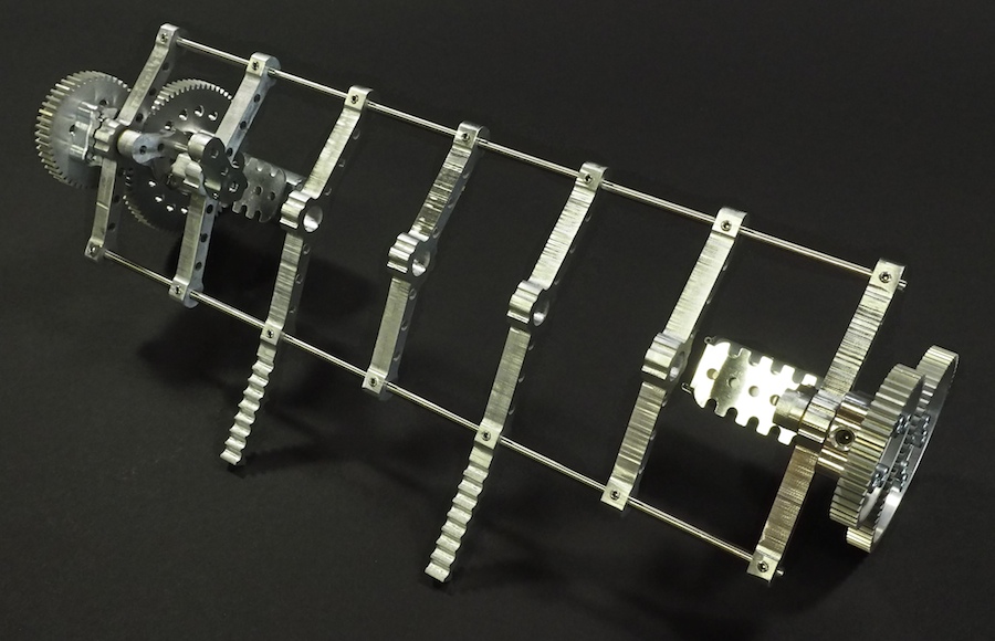
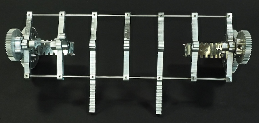
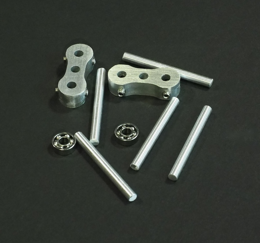
We had good success with our 16-legged walking creature Aluminalis, so we decided to use what we learned and build a new walking creature. We plan for this to be a much smaller, faster, and more agile little beastie. We call her Alumini (Ah-lu-min-ee). Instead of 22″ wide, she’ll be just 10″ wide. Instead of using bulky rectangular segments, we’ve designed much finer segments, like bones in a spine, with built-in pockets for ball bearings to hold the all-important crankshafts. We’ve also designed a custom motor-and-gear mount for each end that holds everything together. Alumini will have twelve legs instead of sixteen. And instead of having a large visible thorax (body), all the electronics will be integrated within and beneath the legs of the robot, so she’ll appear to be nothing but legs. Here are some pictures of our work-in-progress. The crankshaft and legs are not shown. We’re just working on the skeleton and overall structure at this point.
PARTIALLY-CONSTRUCTED SKELETON
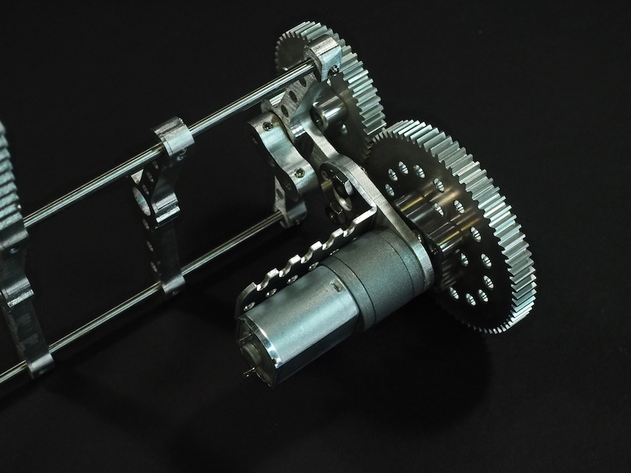
MOTOR AND GEARS MOUNTED ON CUSTOM END PIECE
SKELETON TOP VIEW
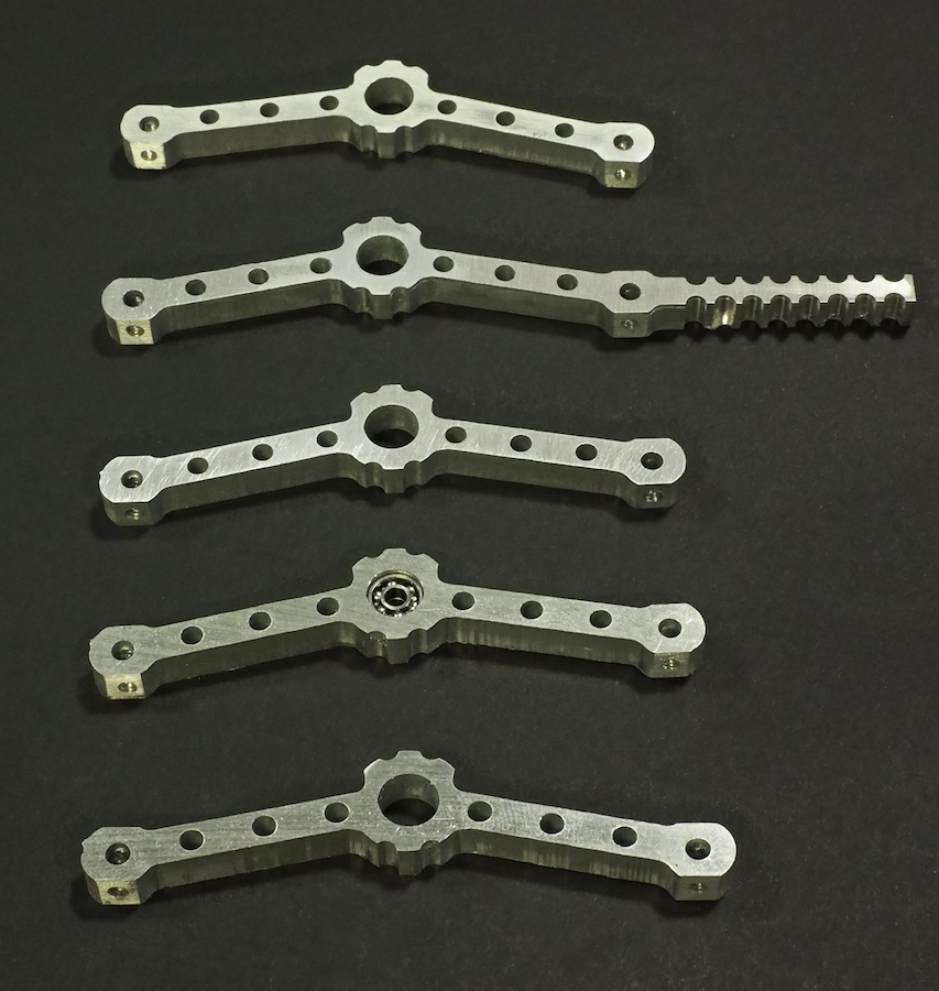
BONE-LIKE SPINE SEGMENTS MACHINED ON CNC
SPINE SEGMENT WITH BALL BEARINGS (TO HOLD CRANKSHAFT) INSTALLED IN SPINE
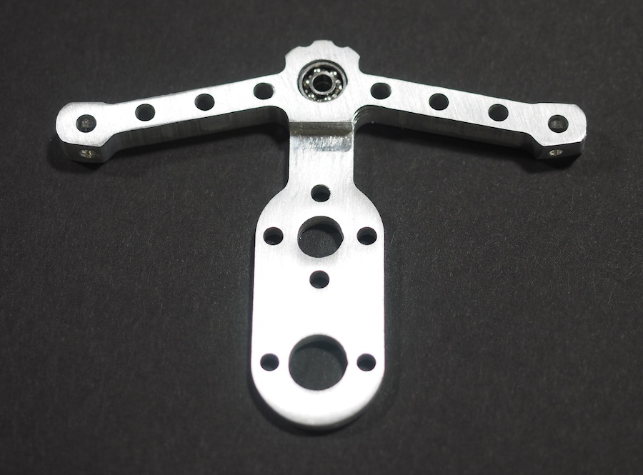
CLOSE-UP OF MOTOR-AND-GEAR MOUNT
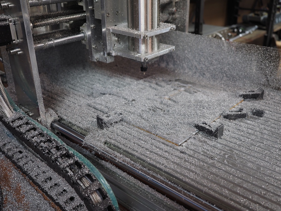
CNC COVERED IN CHIPS AFTER MACHINING THE PARTS FROM A 12″ x 12″ SHEET OF 1/4″ THICK 6061 ALUMINUM
CNC-MACHINED CRANKSHAFT ARMS ALONG WITH BALL BEARINGS AND SHAFTS
We enjoy machining custom aluminum robot parts on our CNC Mill. One of the best things about a CNC is that it can cut precise parts by following the geometry of a CAD drawing. We measure the precision and repeatability of our CNC in thousandths of an inch (0.001). But one of the challenges of using a CNC is to to get the raw material setup properly and make sure the spindle starts at exactly the right position. The CNC can only hold a precise position from its starting point. For example, let’s say you want to cut a pocket that is .050″ deep. That’s easy to do, but you need to start the CNC at the exact surface of the raw material so that it knows how far down along the Z-axis to move the spindle. Or let’s say you need to drill a precise hole pattern in a square sheet of aluminum. That’s easy to do, but you need to start the CNC at the exact corner of the square or your pattern will be way off. Finding the exact starting point is called “zeroing” the CNC. There are whole books written on the subject and a whole sub-industry of gizmos for handling this challenging problem. It took us a while to figure out, but this is what we’ve found to be the best solution for us:
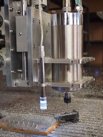
1. When it comes to zeroing out the X and Y position of the CNC at the beginning of a job, we have tried a number of approaches, including eye-balling (not very accurate), mechanical edge finders (don’t like these), and even a laser edge finder (not as accurate and cool as you’d think). For our solution, we installed a super-cool USB camera microscope from our friends at Adafruit onto the frame of our spindle. We mounted the camera using a small aluminum bracket that we designed in SolidWorks and machined on our CNC. We secure the camera bracket to the spindle frame using a 4-40 threaded hole that we tapped for that purpose. The microscope camera points downward toward the raw material. It displays a large, magnified image on the computer screen, including crosshairs. When we want to set the X and Y zero point, we turn on the camera and then move the spindle until the crosshairs line up exactly with the corner of the raw material (or whatever position we want to identify as the zero point). Because it’s a microscope, it’s very precise. We then press the Mach3 “REF ALL HOME” button, which we’ve re-purposed and re-programmed to set the X=0 and Y=0 based on the offset distance between the camera crosshairs and the spindle position. This allows us to quickly and easily zero out the X and Y axis to the exact point we need to.
The microscope camera is the tall, tube-shape thing clamped to the edge of the spindle mount. It has a built-in ring of LED lights to illuminate the subject area.
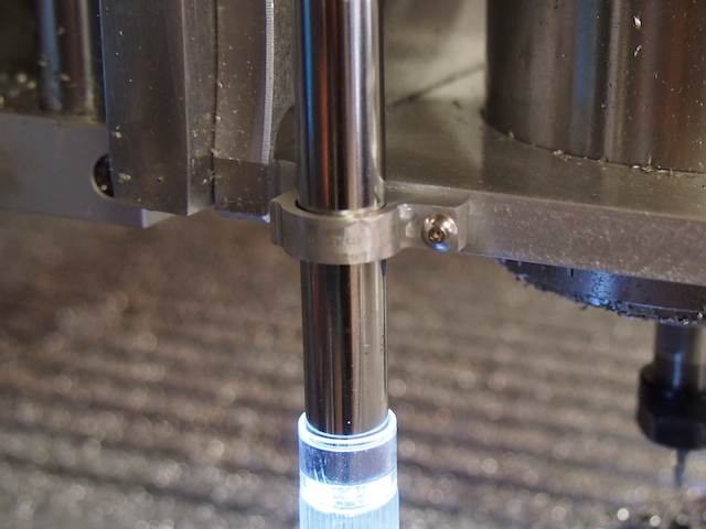
Close-up of the custom bracket we made to hold the tube-shpaed camera to the spindle frame
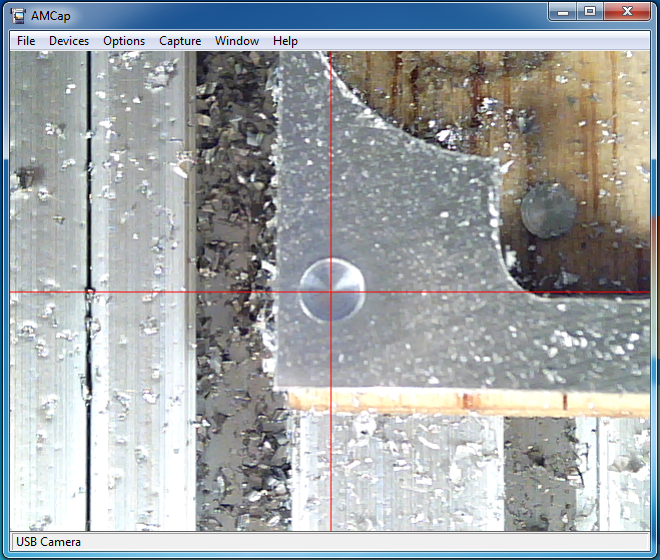
In this situation, we are using the crosshairs of the microscope to zero the CNC to the center of a small hole. The macro will set this as X=0, Y=0.
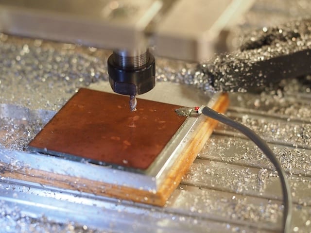
2. The Z-axis, which is the vertical position of the spindle, is by far the most important axis to zero out properly. For this, we rigged up a very cool solution that works great. We cut a piece of copper-clad circuit board (about 1″ x 1″) and soldered it to a long wire that we ran back to one of the 5 volt inputs on our controller. We ran another wire from the base of the CNC. These two wires, combined with the CNC and the end mill (which are both conductive), become like the leads of a voltmeter that is setup to test conductivity. We then wrote a macro in the BASIC language that runs when we press the “Auto Zero Tool” button on the Mach3 interface. When we want to zero-out the z-axis, we place the copper plate on the top of the raw material and press the button. The CNC moves the spindle slowly down toward the plate. The instant the tip of the end mill touches the copper plate the electrical circuit is closed. The macro instantly stops the spindle, sets the Z-axis zero point (by subtracting the .063″ thickness of the plate), and then moves up .125″ so that the copper plate can be removed. The whole process only takes a few seconds to complete. And the result is that the CNC determines exactly where the top surface of the material is and sets it as Z = 0.
The zero plate is placed on top of the raw material. The macro automatically moves the spindle down until the end mill touches the plate and closes the electrical circuit, which signals the CNC to zero the z-axis. Note the wire soldered to the copper plate.
These two techniques have really helped improve our setup time and accuracy.
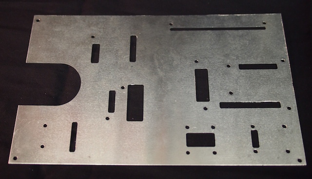
Here we are using our homemade CNC to machine a custom electronics plate for the new Mars Rover we’re building. The robot’s circuit boards and electronic components are mounted onto this plate, which is then mounted inside the robot’s main box. Check out the video and the photos below.
The completed electronics plate for the Mars Rover.
Here is the electronics plate with the various circuit boards and other electronic components mounted. Wiring and soldering comes next. The wires will go through the rectangular holes underneath each circuit board and then run beneath the plate.