by Camille | Workshop Blog
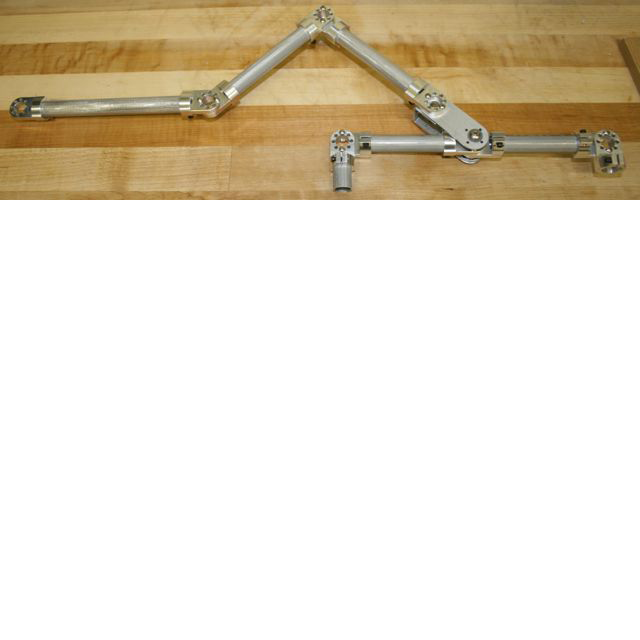
We have been working hard on the rocker-bogie suspension system for the Spirit II, our Mars Rover. In this picture, the front wheel will be attached on the left side. The two back wheels will be attached on the right side. The two back wheels will be connected together by a tube that pivots on its center. The entire thing pivots on a central shaft (connected at the junction second from the left) that goes through the counter-rotating differential to an identical chassis frame on the other side of the robot. We are building the chassis frame out of .625 aluminum tube, tube connectors, and aluminum plate. It takes a bit of imagination at this point to visualize how this is going to become a Mars Rover, but it’s coming along. If it all actually works, we’ll be amazed.

Mars Rover Chassis – in process
by Camille | Workshop Blog
We are currently building a rover similar to the Mars Rovers Spirit and Opportunity, which we have always loved (but have been way outside our skillset in the past).
We have been studying the details of the rovers, their electrical systems, chassis, wheels, and so on. Ours won’t be exact, of course, but hopefully, if all goes well, it will be a nice working model, including the solar panels.
One of the most unusual and characteristic elements of the Mars Rover design is what they call a rocker-bogie suspension system (http://en.wikipedia.org/wiki/Rocker-bogie), which is intended to help the rover go over rocks. This system involves six wheels, with a special interconnection between the various wheels so that at least one or two of the wheels on each side are on the ground at any one time, even when going over obstacles. It took a while to figure it out, but this design requires a connection between the wheels and each side such that when the wheels on one side go up over a rock the wheels on the other side go down and vice versa. NASA uses what they call a “differential” (although it’s not the same as a car differential).
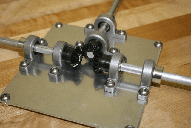
Anyway, we couldn’t find a counter rotating differential that met the requirements, so we decided to make made one. We’ve attached a picture. The plate, pillow blocks, and shafts are made out of aluminum. There are three bevel gears, which are made out of steel. This gear box will go inside the center of the robot’s main box directly between the wheel sets on each side. The way we’ve meshed the gears together creates a counter rotating shaft so that when one side goes up the other side goes down.

Counter Rotating Differential for Mars Rover

From Above

Close up of bevel gears
by Camille | Gallery, Robots, Slider, Workshop Blog

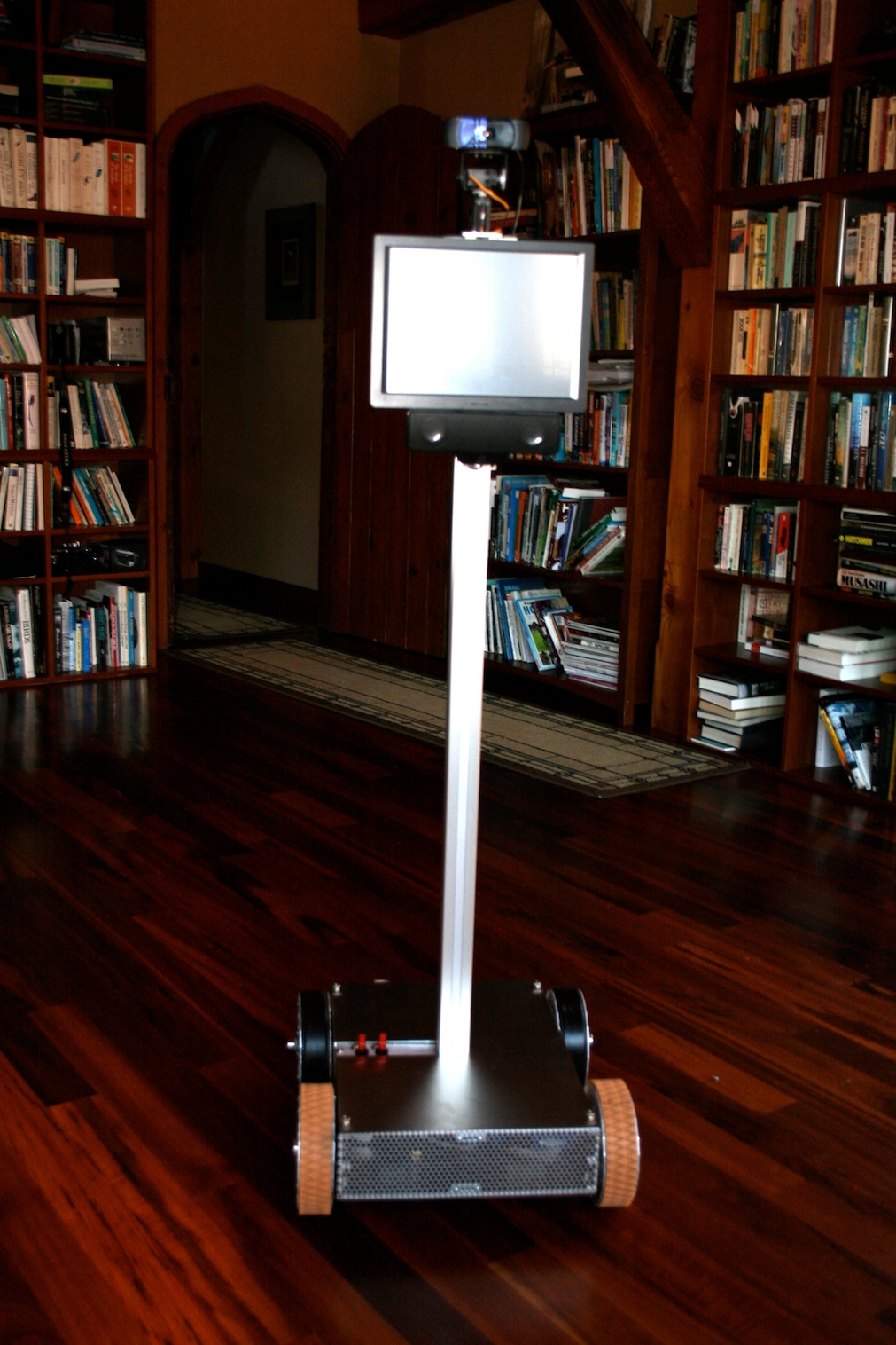
This is Telegance. He is a Telepresence Robot, which means he’s a driver-controlled mobile video conferencing system.
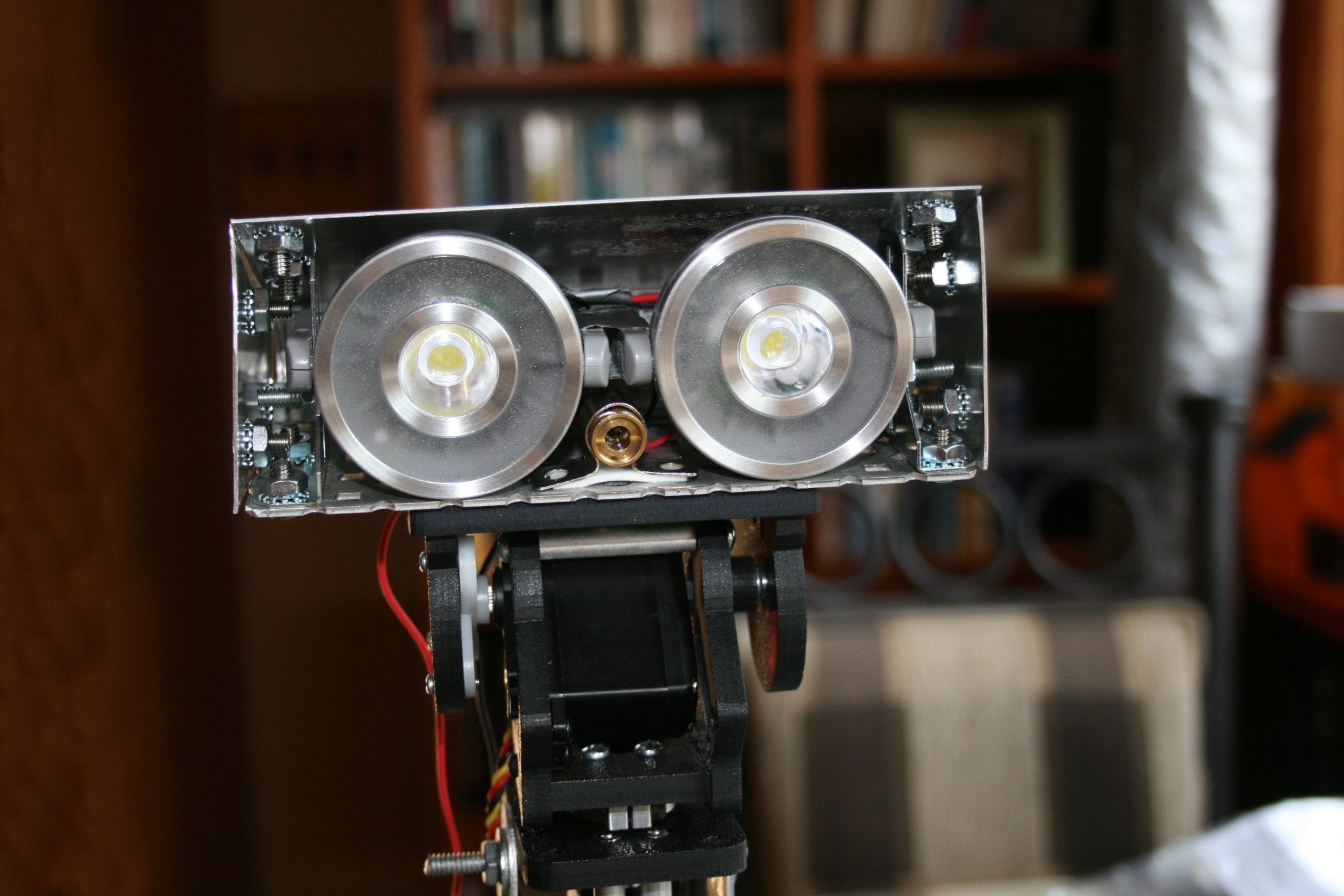
Imagine I’m out in the world. I can use my laptop or any other computer to link into the robot through the Internet. The people around the robot see my face on the robot’s screen. The sound of my voice comes through the speakers, which are mounted just below the screen. I hear through the robot’s microphone and I see through the robot’s camera, which is mounted on two little servos, so I can tilt and pan the camera where I wish to look. I can drive the robot around the house, to the kitchen or the bedroom or where ever, using the robot’s built in motors. His wheels are designed to drive or turn on carpet, tile, and hardwood floors.

Side View of Base

How We Built Him
Telegance was a lot of fun to build, but he was definitely one of our most challenging robots so far. We learned a lot. Telegance is our first robot that is based on a computer rather than a microcontroller chip/board. Our vision was to build a robot based on a Mac. So, we grabbed a Mac Mini, tore it apart, ripped everything off that we didn’t need, rewired it for DC (it was an AC computer), and replaced the conventional hard drive with a Solid State Drive (SSD) (so that we didn’t need a fan, it didn’t make any noise, and it used less power). We installed just the stripped down motherboard into the base of the robot. When it booted up it was silent, fast, and ran on 12 volts like the rest of the robot. We then connected this to an Arduino Mega microcontroller through a USB cable. The Mac Mini, which runs a special Skype plugin, handles the webcam videoconferencing (using Skype), the touch screen, and 802.11b networking. The Arduino handles the drive motors, the webcam pan-tilt servos, power distribution, and other robotic features. We constructed the robot’s frame in our workshop using raw aluminum plate and c-channel. We especially like the cool wheels on this robot.

Touchscreen, Webcam on Tilt-Pan Servos, and Speaker: Telegance Robot

Under the Hood: Mac Mini motherboard (left), Arduino Mega Microcontoller (right), Sabertooth Motor Controller, Xbee Radio
by Camille | Robots, Slider, Workshop Blog
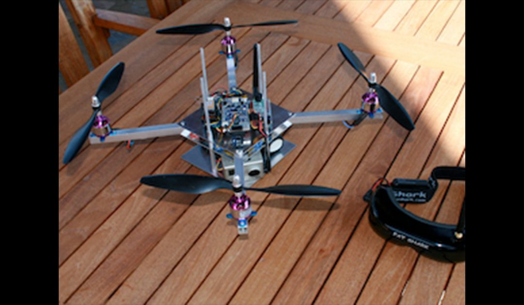
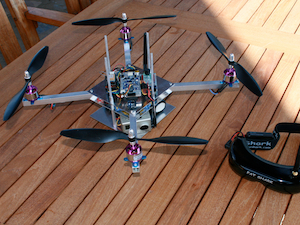
We would like to introduce our flying drone robot. We can fly this robot using Remote Control or it can fly itself using sonar, an on-board GPS, and following longitude/latitude waypoints. We have experimented with various frame designs and electronics, so you’ll see some variation in the pictures. Be sure to check out the video of of me piloting the flying robot.
How We Came To Build a Flying Robot Drone
One day, we asked ourselves, “What kind of robot would you like to build next?”
We both answered, “I want to build a robot that flies!”
We knew it was going to be really hard, but we decided to give it a try. We set out to learn what it was going to take to build a robot that flies. We researched our options, purchased the various motors, propellers, and electronic components we thought we needed, and started soldering. As our initial design came together, we began cutting, drilling, and assembling the various aluminum pieces for the frame, which we knew would have to be both light and strong.
The Features and Design
We decided on a quad rotor design, which is a helicopter-like-thing with four propellers. The left and right motors use normal “puller” propellers and turn counter-clockwise. The front and back motors use “pusher” propellers and turn clockwise. This helps counter-act the torsional forces associated with rotor craft.
The core of the robot’s electronics is a special Arduino microcontroller board specifically designed for auto-piloting drones. This is combined with a special Inertial Measurement Unit (IMU) sensor shield that provides a 3-axis gyro, 3-axis accelerometer, barometric pressure, and other various other avionics sensors so that the robot can sense its tilt, pitch, and yaw in three-dimensional space at all times. The software reads the robots orientation and feeds voltage to each of the motors in proportion to the power that is needed to keep the robot level at all times. This way, the pilot focuses on the direction and speed he wants to go, rather than spending all his time struggling to keep the robot from flipping, spinning, or rolling.
Once we flew and crashed our first design, we made some improvements and tried again. Then we crashed again, made some more improvements, and so on. None of our robots have required more trial and error than this one. But step by step, improvement after improvement, our robot got better and better. Today, it flies very well, has many neat features, and thanks to repeated practice, is relatively crash resistant.
We usually fly the robot using an RC Transmitter. However, it also has many autopilot drone features that we enjoy experimenting with. For example, the robot has an automatic take-off and landing sequence. The robot also includes a downward-facing sonar so that the robot knows its exact altitude at all times. By flipping a switch on our transmitter, we can put the robot in “hold altitude” mode, which tells the robot to automatically and constantly adjust the motors to remain at a constant distance from the ground as we fly it around.The robot is also equipped with a GPS chip so that it knows its exact longitude and latitude at all times. The robot can also follow a series of waypoints uploaded to the microcontroller from Google Earth. It turns out that we were not the only ones trying to build a robot that flies. We have joined with a whole community of people on the Internet (DIY Drones) who enjoy building and flying their own robot drones.
The Mini Flying Drone
We have also built a Mini Flying Drone. Click here to see details.

Mini Quadrotor Drone Robot
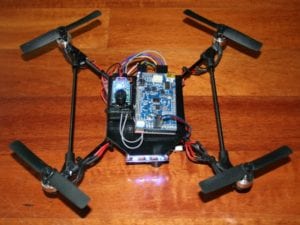
The upgraded Black Hornet mini drone
The Future
Although our drones are flying quite well, there is still plenty more we want to do. We look forward to lots of fun and experimentation. We’ve spent most our time building, flying, and improving the robot’s frame and capabilities, but in the future we hope to do more with First Person View (FPV) flying using our video goggles, high-definition arial photography, automatic navigation, and more.
Click here to see our latest flying robot drone, which we made out of carbon fiber.
Flying Drone Robot – Technical Specifics
- Aluminum Frame: Beatty Robotics
- Aluminum, Hardware, and other materials: McMaster-Carr
- Microcontroller: ArduPilot Mega (i.e. Arduino Mega Autopilot board)
- Avionics sensor board: ArduPilot Mega IMU Shield
- Electronic Speed Controllers: (4) m2mPower
- Motors:(4) jDrones
- Propellers: (4) EPP 10×45
- Radio Control Transmitter and Receiver: Futaba
- Battery: 12v 3-cell 20C LIPO
- Magnetomer: DIY Drones
- GPS: MediaTek
- High Definition Camera: GoPro
- VideoTransmitter: ImmersionRC
- FPV Video Goggles: FatShark
Special thanks to the Do-It-Yourself Drones community, especially Chris Anderson, Jani Hirvinen, and the other guys involved with DIY Drones. You guys helped us make our dream of a flying robot a reality. Fly on!
by Camille | Robots, Workshop Blog
For the story of our first little robot, I.C. 12, please visit the About Us page.
OUR FIRST ROBOT: I.C. 12

A proud roboticist holding her first robot (I.C. 12)

I.C. 12 on the workbench


