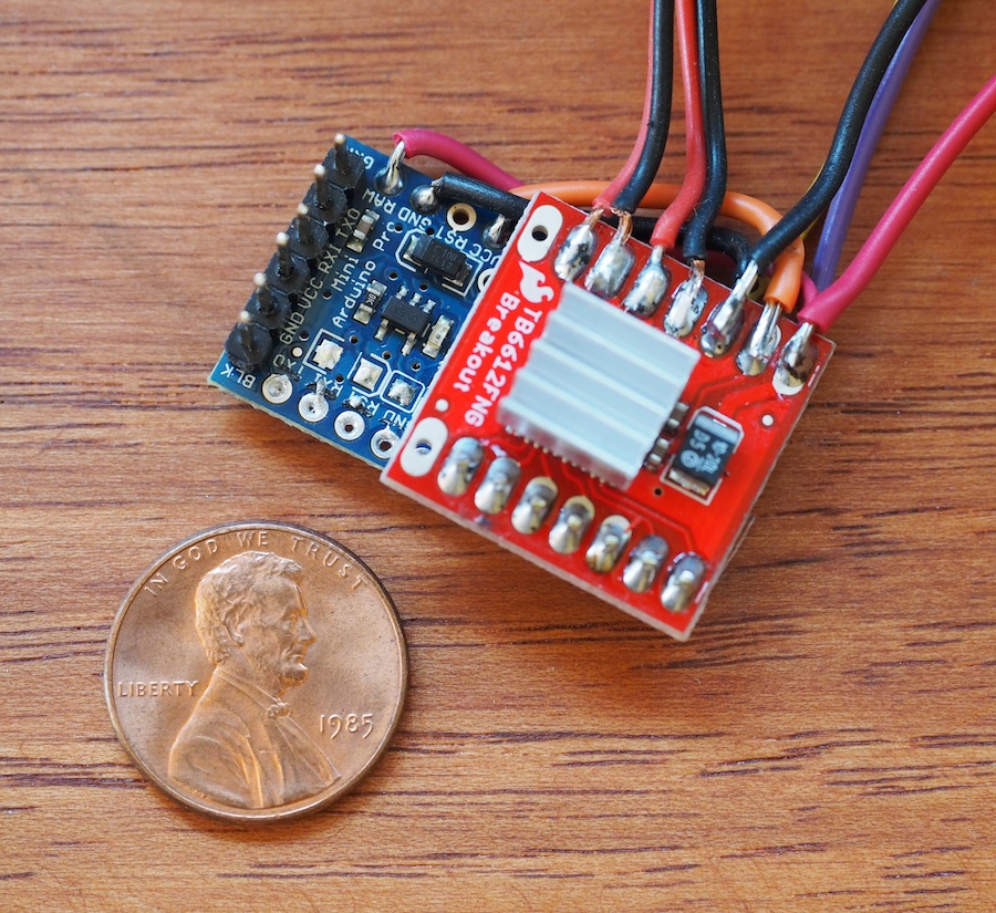
Recently, we encountered a situation where we needed a very small Arduino microcontroller and motor driver. On Alumini, our 12-legged walking robot, there won’t be an electronics box, so we will be integrating the electronics into the bones of the creature. Our goal was for the creature to appear to be all legs. So, we needed the electronics to be very small, hidden beneath and between the robot’s many leg linkages. After trying a few experiments with different components and approaches, we’re excited about the approach we came up with. We don’t know whether it’s going to work in the final robot yet, which is still under construction, but so far it seems promising. The Arduino Pro Mini board from Sparkfun is just 0.7″ x 1.3″ and it’s on a 0.032″ thick circuit board, so it’s a very small, thin little microcontroller indeed. We love the form factor. If it works on this project, it may just become our “go-to” microcontroller for small projects. We also decided to try Sparkfun’s tiny 1A Motor Driver, which is only .8″ x .8″ square.
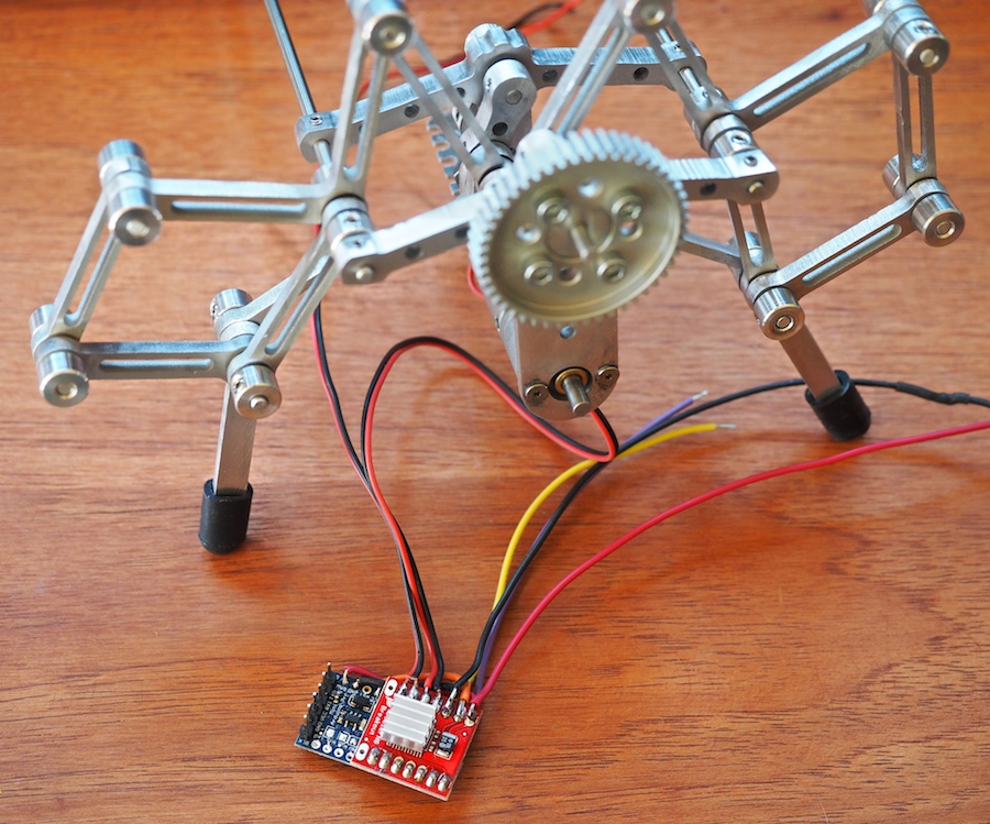
Genevieve and I soldered up the boards and they’re working well so far, but the one negative we’ve encountered is that the motor driver is a very simple little thing. It’s basically just a breakout board for the TB661FNG chip, so it doesn’t have a lot of on-board smarts. Instead of a single TTL serial wire like we’re used to, it requires 2 PWM pins and 5 digital pins to control it. We don’t have a lot of room for wires, so we did something we thought was really cool: we sandwiched the boards together and turned the motor driver into a tiny make-shift shield for the Pro Mini board. We lined up the pins just right, wrote the software to correspond to those pins, and literally soldered the boards together, which eliminated the need for the 7 control wires. We thought there was a fair chance we would ruin the two boards, but it worked like a charm. In the photo, the seven solder points near the penny (on the red board) are the control pins between the arduino and the motor driver. The other wires (at the top of the photo) go to the 11.1V LIPO battery, motors, sonar sensors, xbee radio, and other components of the robot.
The next big question is whether this little motor driver, which is rated at 1.2A per channel can handle Alumini’s 20mm x 42mm metal gearmotors, which are rated for a free-run current of 0.25 Amp and a stall current of 3.3 amps. Normally we would use a 5A motor controller for these motors, but the 5A motor controller was too large to fit on Alumini’s delicate frame. Once we had soldered our mini robot control system together, we were able to do some testing. When we run the partially-completed Alumini robot on the bench, the motors are pulling .6 Amp each, but they don’t have much force on them yet. We’ll see how this goes once we get Alumini scuttling at high speed around the room. We may end up smoking the motor driver and going back to the drawing board. We thermal-pasted a tiny aluminum heat fin to the chip to help dissipate the heat. We’ll keep you posted.
If you know of any small microcontrollers and motor drivers that would be good for our purpose, please let us know. We would love to know how you’ve solved these problems on your projects.
We’ve been hard at work on several simultaneous on-going projects, including an upgrade to our large Mars Rover, the building of two new Mini Mars Rovers for two science centers in Kuala Lumpur (The National Science Centre and Petrosains, the Discovery Centre), a large tread-based laser tank (which is super-cool, but we haven’t had a chance to post it yet), and Alumini (our 12-legged walking creature).
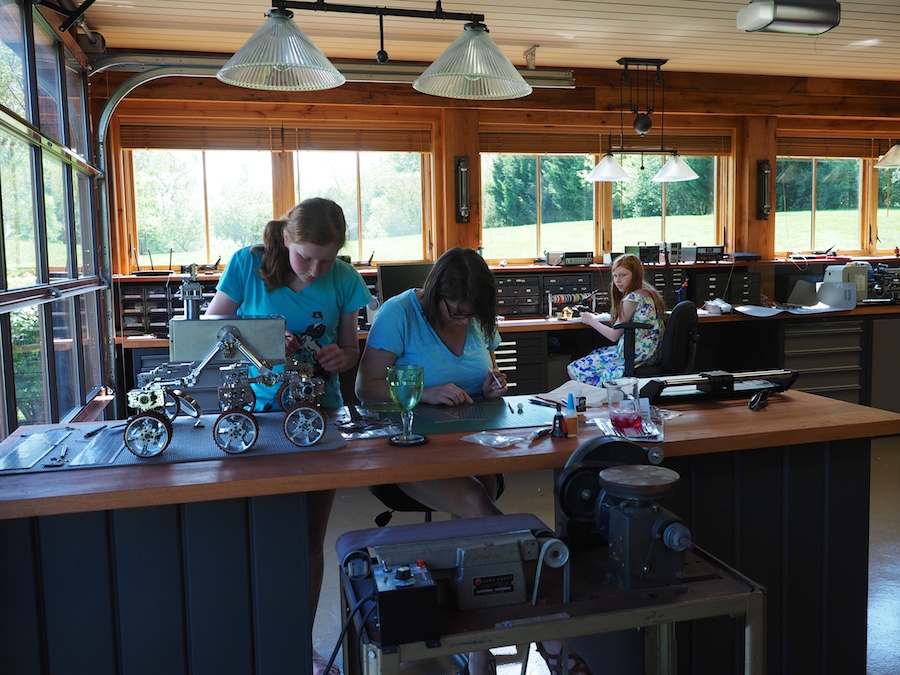
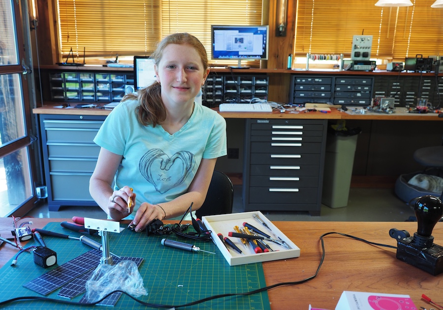
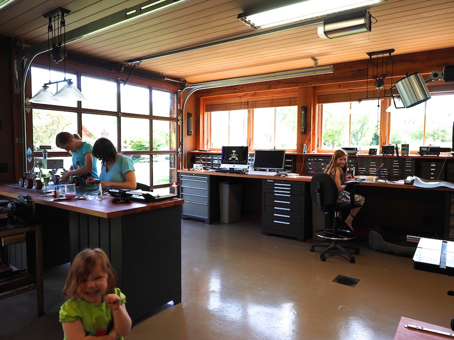
Here are some pictures of the ladies at work in the workshop.
JENNIFER INSTALLING THIN FILM SOLAR PANELS ON THE TOP PLATE OF A MINI MARS ROVER WHILE CAMILLE WORKS ON UPGRADING ONE OF THE FULL-SIZE MARS ROVERS
GENEVIEVE BUILDING ONE OF THE MINI MARS ROVERS
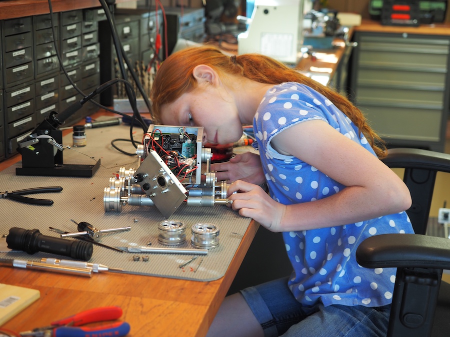
CAMILLE WORKING ON THE CAMERAS FOR THE MINI MARS ROVER
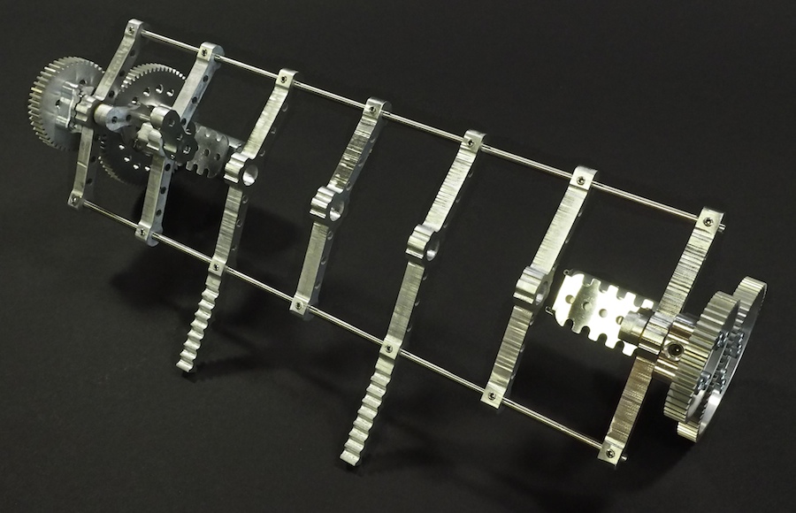
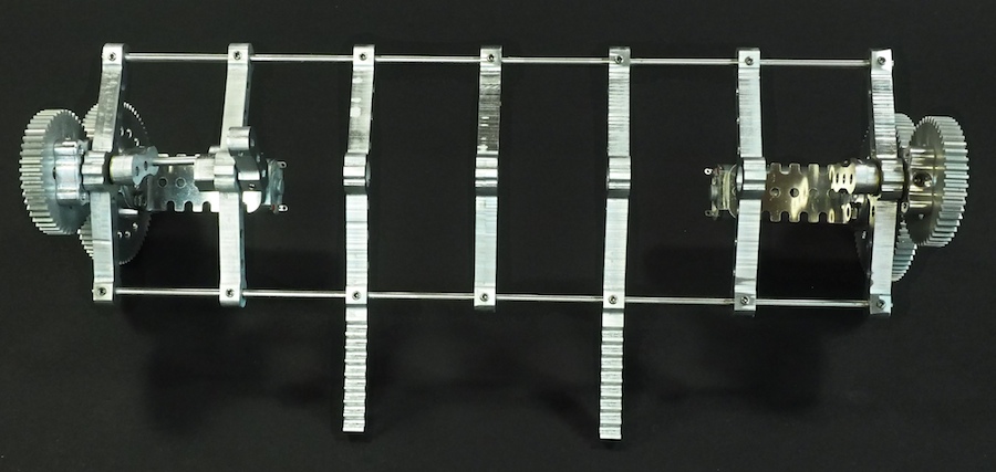
We had good success with our 16-legged walking creature Aluminalis, so we decided to use what we learned and build a new walking creature. We plan for this to be a much smaller, faster, and more agile little beastie. We call her Alumini (Ah-lu-min-ee). Instead of 22″ wide, she’ll be just 10″ wide. Instead of using bulky rectangular segments, we’ve designed much finer segments, like bones in a spine, with built-in pockets for ball bearings to hold the all-important crankshafts. We’ve also designed a custom motor-and-gear mount for each end that holds everything together. Alumini will have twelve legs instead of sixteen. And instead of having a large visible thorax (body), all the electronics will be integrated within and beneath the legs of the robot, so she’ll appear to be nothing but legs. Here are some pictures of our work-in-progress. The crankshaft and legs are not shown. We’re just working on the skeleton and overall structure at this point.
PARTIALLY-CONSTRUCTED SKELETON
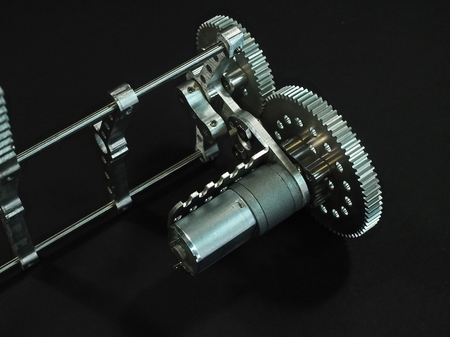
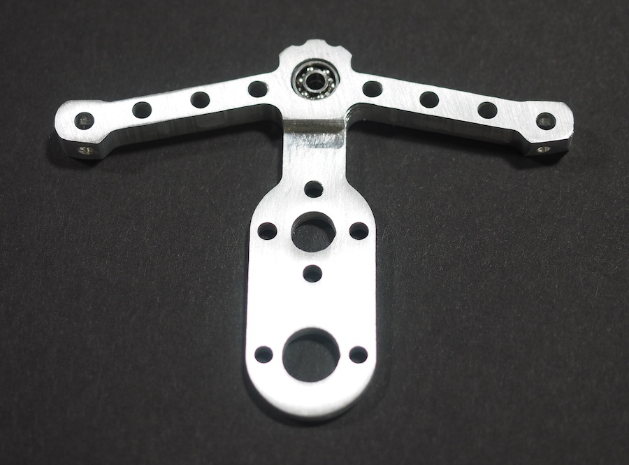
MOTOR AND GEARS MOUNTED ON CUSTOM END PIECE
SKELETON TOP VIEW
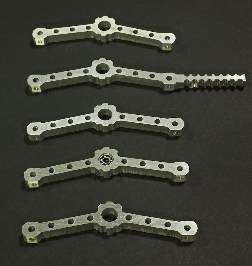
BONE-LIKE SPINE SEGMENTS MACHINED ON CNC
SPINE SEGMENT WITH BALL BEARINGS (TO HOLD CRANKSHAFT) INSTALLED IN SPINE
CLOSE-UP OF MOTOR-AND-GEAR MOUNT
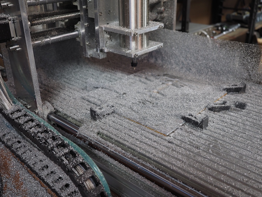
CNC COVERED IN CHIPS AFTER MACHINING THE PARTS FROM A 12″ x 12″ SHEET OF 1/4″ THICK 6061 ALUMINUM
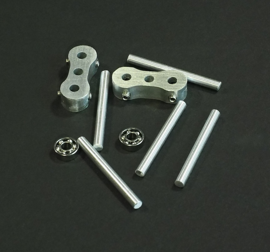
CNC-MACHINED CRANKSHAFT ARMS ALONG WITH BALL BEARINGS AND SHAFTS
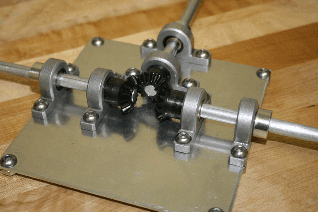
Back in November of 2011 we posted an article about our first Spirit II Mars Rover. Among other things, that rover included a counter-rotating differential (or universal joint) integrated into its rocker-bogie suspension system. If the front wheel on the left side of the rover went upward over a large obstacle, then the differential would push the three wheels on the right side downward, and vice versa. Its purpose was to stabilize the rover when traversing rough terrain. We made that first counter-rotating differential from bevel gears, aluminum rods, aluminum plates, and screws. Its shafts were connected to each side of the rocker-bogie suspension system. The function was simple: If either of the shafts rotated, then it caused the other shaft to rotate in the opposite direction. Our original version worked quite well, but it was also large, bulky, and a bit difficult to keep running smoothly.
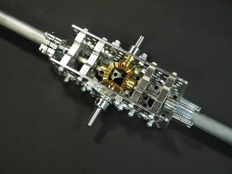
Recently, our friends at Actobotics / ServoCity sent us a couple of their new bevel gears to try out. It’s cool how a few new parts can fire up your imagination and get you thinking. We decided to see if we could create a new counter-rotating differential for a future Mars Rover project. We were very pleased with the results. The new differential is much smaller than the old version, so it will fit nicely inside the box of a Mars Rover, and its operation is smooth and robust. Camille took all the photos of the new differential.
THE NEW COUNTER-ROTATING DIFFERENTIAL
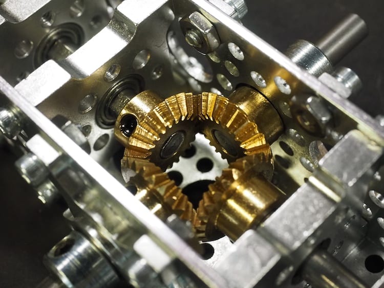
CLOSE-UP OF THE NEW COUNTER-ROTATING DIFFERENTIAL
CAMILLE’S ARTISTIC BACK-LIT SHOT OF THE COUNTER-ROTATING DIFFERENTIAL
OUR ORIGINAL COUNTER-ROTATING DIFFERENTIAL
THE ORIGINAL DIFFERENTIAL IN THE PARTIALLY COMPLETED SPIRIT II MARS ROVER. ONLY THE LEFT-SIDE WHEELS ARE IN PLACE.
In 2014, President Obama invited us to the White House! It was amazing to walk into the White House and set up our robots in the Grand Foyer. The President and many others came through to talk with us and see our robots, including cabinet members, senators, CEOs of tech companies, deans of universities, and techno-dignitaries from across America. We met and talked with the Director of the National Science Foundation (NSF), top officials from NASA and the Navy (who tried to recruit me!), Dean Kamen (inventor of Segway, FIRST Robotics, etc.), Dale Dougherty (Founder of MAKE Magazine & Maker Faire), and many others. The famous rapper/activist will.i.am drove our Mars Rover around the White House! But the best part was when everyone poured into the East Room and the President gave a big speech to the nation. He talked about us as shining examples of American entrepreneurialism. When he asked us to standup, the whole room burst into applause. It was awesome. —Genevieve & Camille
Here we are in front of our robot exhibit in the Grand Foyer of the White House…
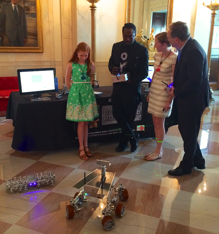
Our robot exhibit in the Grand Foyer of the White House…
Here we are with Dale Dougherty, CEO of Maker Media, founder of the Maker Faire, and publisher of MAKE Magazine.
Beatty Robotics in front of the famous portrait of JFK in the White House.
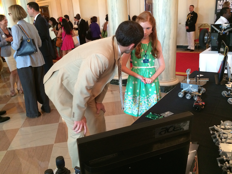
Hundreds of dignitaries and VIPs attended the event. Here, Genevieve is explaining the technical details of the robots to one of the visitors.
The famous rapper/activist will.i.am is committed to science education in the inner cities, so he was one of the people who dropped by our exhibit. We taught will.i.am. how to drive the Mars Rover and our Aluminalis robot around the Grand Foyer of the White House! will.i.am showed intense interest and knowledge in the technology of robots and we talked in detail about his involvement in FIRST robotics and other society-oriented initiatives.
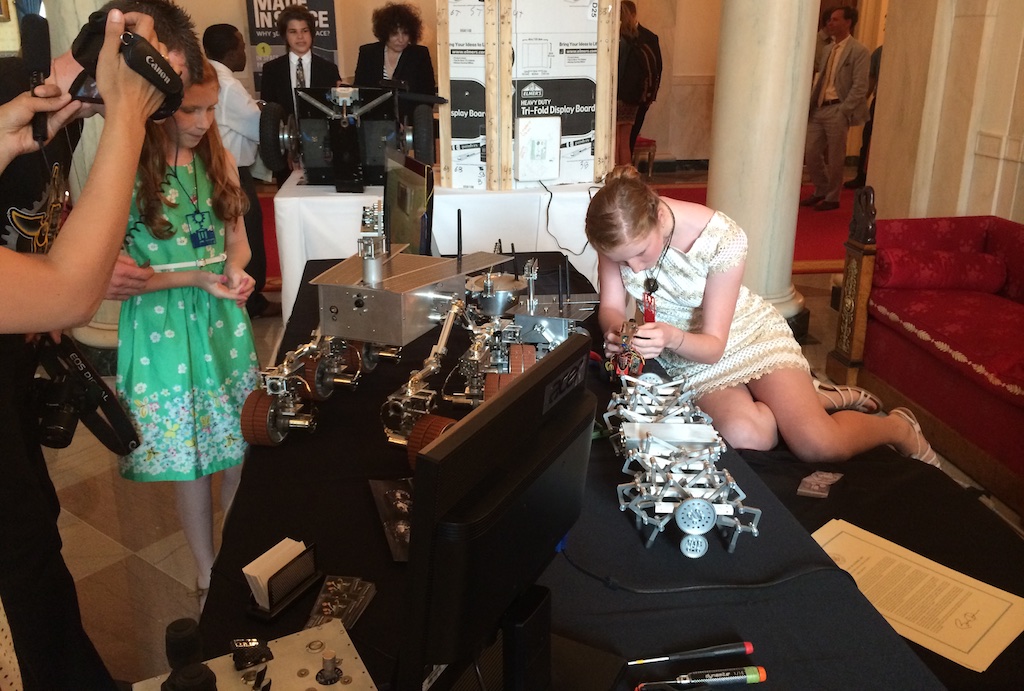
Here is Camille making a little electronic tweak to one of the robots while Genevieve talks with one of the visitors…
It was a great honor to be invited to the White House and to be part of this historic event. We would like to thank the New York Hall of Science for their encouragement and support, and for lending us their “Genevieve” Mars Rover for a few days. We would also like to thank the staff at the White House, all of whom were warm, welcoming, and excellent to work with. We would also like to thank our mom for remembering to take pictures with her iPhone during the exciting chaos of the event. —Genevieve & Camille