My sister Genevieve is an expert solderer. Her hands are small, steady, and well practiced. Here is a picture of her soldering a voltage regulator for our Spirit II Mars Rover project.
Genevieve soldering
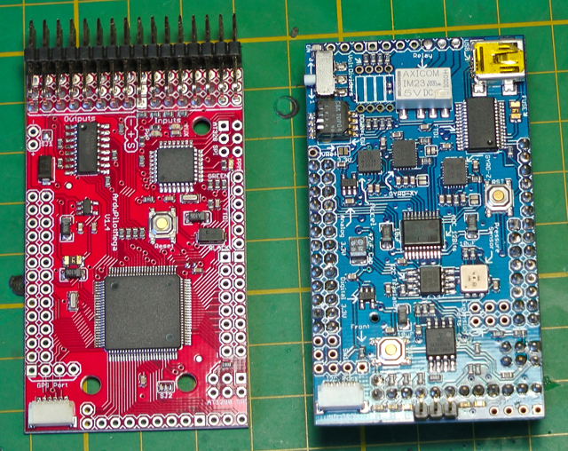
Here is a one minute video of Genevieve soldering the header pins onto a circuit board. We use this circuit board, which has more than a hundred solder points, on our flying drone robot. Note that she is using the proper technique by applying the tip of the soldering iron to the pin and hole, then bringing in the solder from the side.
CREDITS:
Solderer: Genevieve (9 years old)
Director & Videographer: Camille (11 years old)
Editing: Camille, Genevieve, and R.
We have been hard at work on our latest project called Mechatron. To control our Mechatron robot as well as our Mars Rover, we designed and built our own remote control box. We developed our own communication protocol for transmitting commands from the remote control to the robot. On other projects we used iPhones and Playstation remote controllers, but in this case we wanted to build a large, metal box with lots of retro-switches and joysticks.
1. Although it wasn’t cheap, the hall-effect 3-axis joystick was critical for controlling the function of Mechatron’s specialized drive system. We originally tried a traditional analog/resistive/potentiometer-style joystick and it did not work well at all. We thought our whole project was going to fail until we realized that not all joysticks are created equal. The joystick based on the “hall-effect” principle worked perfectly for us.
2. You can’t see it in these photos, but this controller can be charged via banana jacks and re-programmed via a USB jack without having to unscrew and remove the case. The same is true for the Mechatron robot itself.
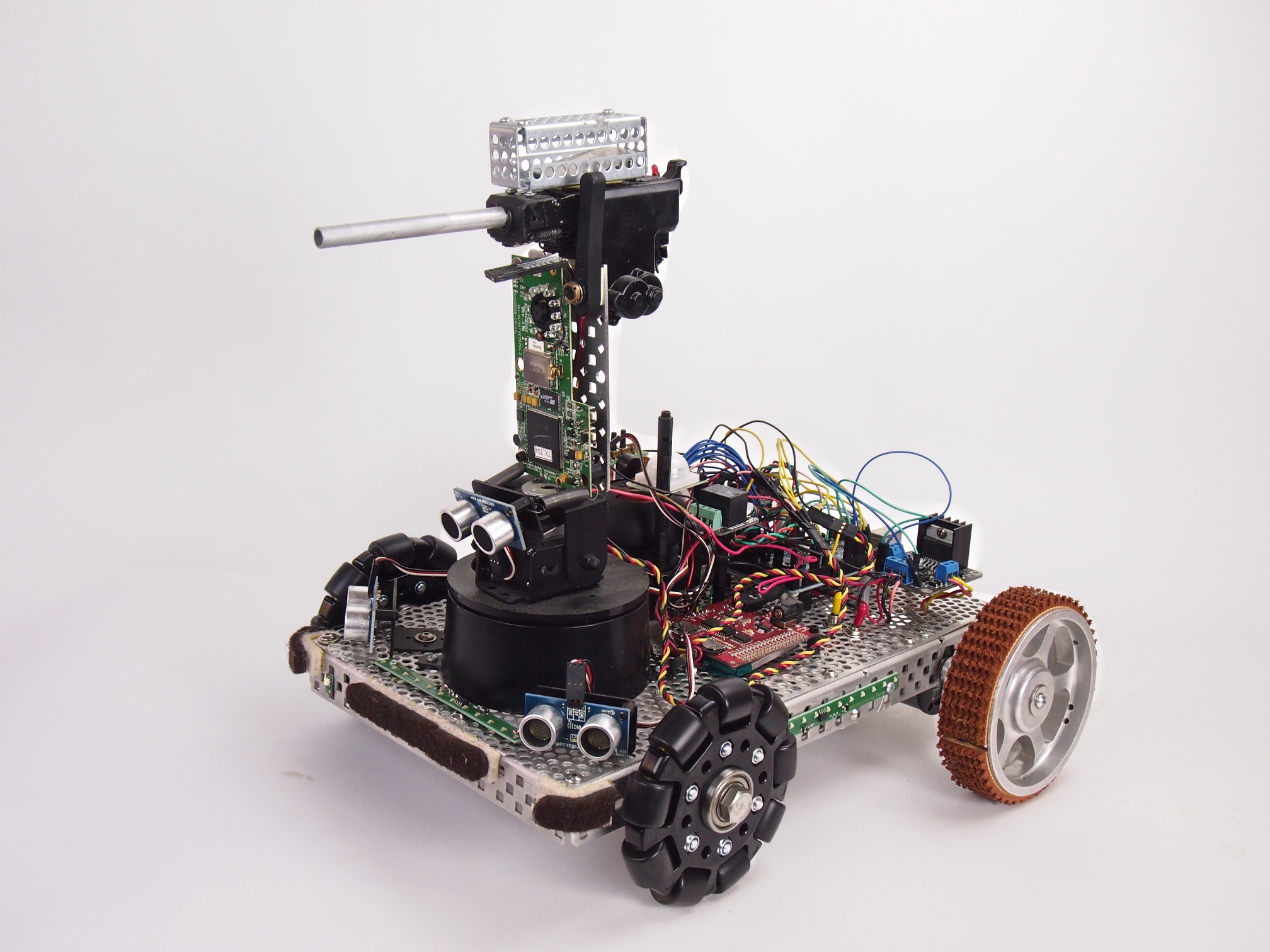
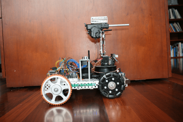
Security V is a small security robot. It’s equipped with the following capabilities:
Automatic electric gun (Airsoft pellet gun) with ammunition cage
Pan-Tilt Gun Turret
Targeting laser
FPV Camera
(3) Ping sensors for object avoidance
LED Light Strips
MP3 Sound Player
IR Human Detection Sensor
Moto Controller
Two motors
Two treaded drive wheels and two omni wheels
Arduino Mega Microcontroller
Xbee Radio for remote control
Button panel for selecting the mode
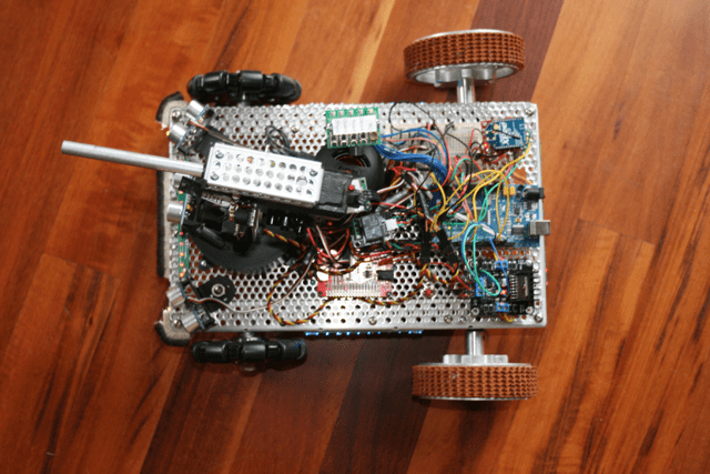
We programmed it with five different modes:
1. Roams autonomously around the house, playing R2-D2 like sounds as it explores & avoids obstacles 2. Remote Control 3. Dance Mode (Plays the song Mr. Roboto and dances around) 4. Guard Mode (enables its infrared human detection sensor and plays a police siren if anyone tries to sneak past it) 5. Shoot (shoots the gun)
Security RobotSecurity RobotSecurity Robot – Top View
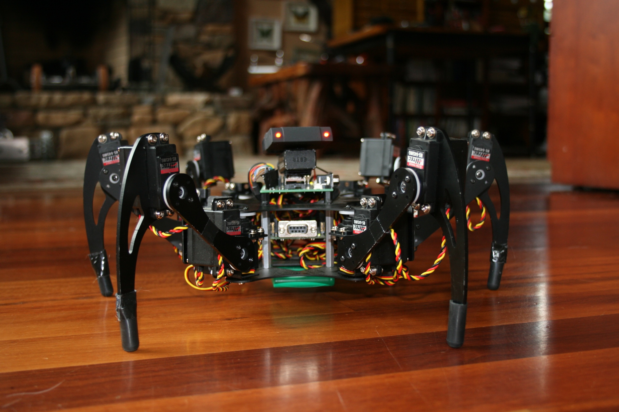
Having created several robots that roll on wheels of various kinds, we decided to build a robot that walks, or more accurately, crawls, in a spider-like fashion. We call him Creepy Crawler. We control this robot using a PS/2 remote control. Each leg has three Degrees of Freedom (DOF) so his gate and other movements are very creepy and biological. To create Crawler’s head, we hacked into a PS/2 receiver and installed the red receiver lights (LEDs) so that it looks like he has glowing eyes.
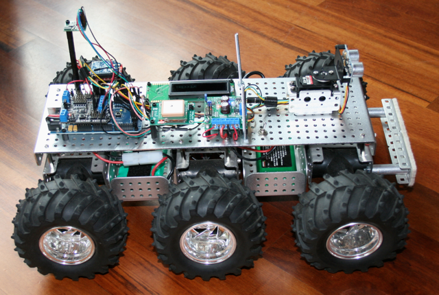
After building a number of indoor robots, we decided to build an outdoor robot capable of traveling through rough terrain. We call it “Trekker.”
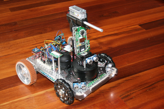
TREKKER ROBOT. Six wheels. Six motors. Batteries below deck. Electronics above deck.
First, we put together a six-wheel independent suspension with a separate motor on each wheel and large knobby tires. Each wheel moves up and down separately, which allows this little beast to climb up and over just about any obstacle (rocks, slopes, cats, whatever gets in its way). Here is a video of Trekker going over a large pile of books.
This is by far our funnest robot to drive via Remote Control, but this true magic of Trekker is his navigational capabilities.
We wired Trekker with a GPS chip and a tilt-compensated magnetometer (an electronic compass that works even when the robot is tilted). When Trekker first comes on, he automatically looks for and synchs with as many satellites as he can find in the sky (usually about 10-15). We programmed Trekker to determine his exact latitude and longitude position using the GPS as well as his directional orientation using the magnetometer. He then travels on his own to a series of latitude and longitude waypoints (that we get from Google Earth). Trekker’s navigational algorithm was one of our most ambitious software challenges to date. Our favorite test run is to put him in our backyard and give him instructions to drive around the big tree, down to the barn, drive around the goat pen, and return to us. He does it beautifully, all on his own, moving systematically from one waypoint to another. We also equipped him with a forward-facing sonar, which swivels back and forth on a pan servo, to avoid trees and other large obstacles along the way.
Trekker Robot – Top View – The white square in the middle is the GPS, which is used for navigation. When traveling between waypoints, the Longitude and Latitude display on the little LCD screen.
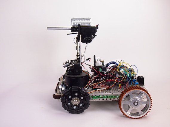
Trekker – Front View – This provides a nice view of the sonar at the front of the robot, which is used for obstacle detection and avoidance when traveling in automated mode. The magnetometer (compass) is mounted on a tall shaft at the back of the robot to keep it clear of interference from the other electronics, especially the radio.
This picture of Trekker’s underside shows how each wheel connects to a separate motor (black t-shaped things). Each motor housing is on springs and swivels so that it moves separately from the other motors.
Thanks to the shock-absorbing independent suspension of each of its six wheels, Trekker rolls over pretty much anything
Software Modes
We programmed Trekker with a several different modes he can operate in:
Navigate autonomously to a series of user-provided Longitude/Latitude Waypoints
Roam autonomously using swiveling front sensor to avoid obstacles and find best path
Radio Control (RC) – display commands and motor speeds on LCD
Radio Control (RC) – display longitude, latitude, and heading on LCD