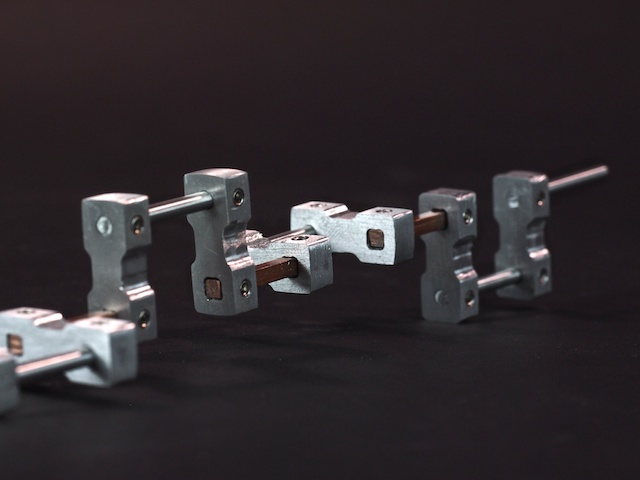
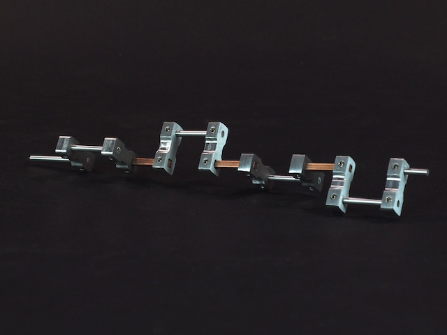
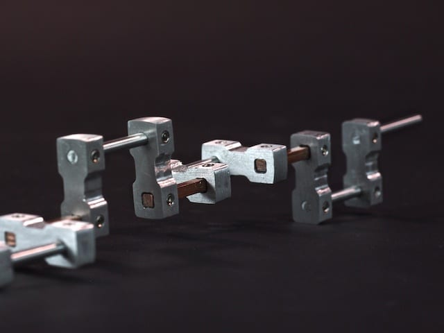
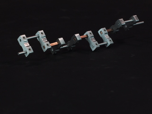
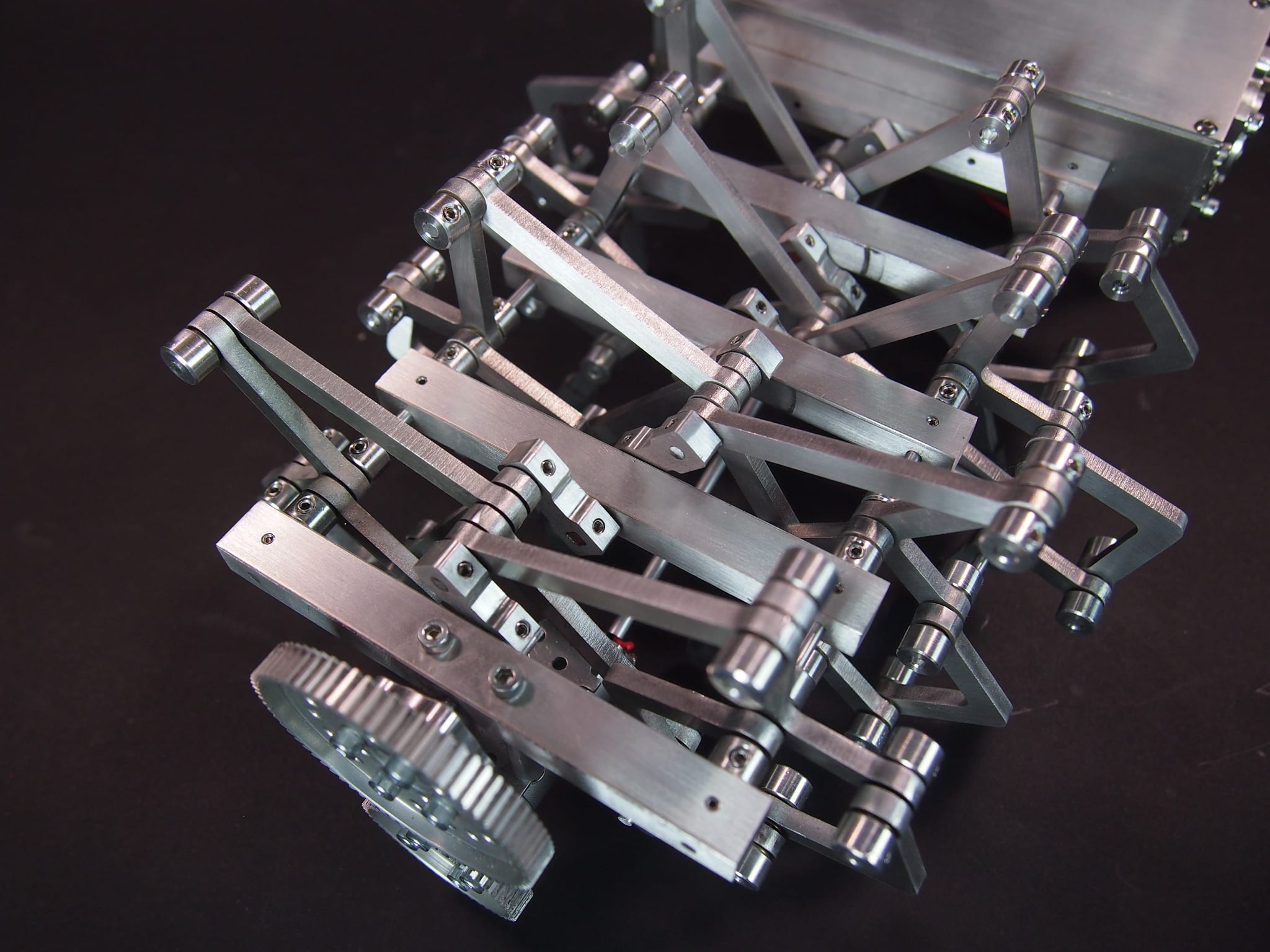
One of the funnest, but most challenging parts of building Aluminalis (our 16-legged walking robot) has been the construction of the two crankshafts. Each side of the robot has a motor that rotates a 10” long, multi-link crankshaft, which drives 4 pairs of legs. The leg pairs need to be kept 90-degrees out of phase from each other in order to produce the walking gait. Our initial vision for the crankshaft was to build it out of 1/8” aluminum round shafts, custom crankshaft arms we made on our CNC, and tiny 4-40 set screws, but when we put it all together for real-life testing, the rotational forces were so high that the set screws couldn’t hold the round shafts, the crankshaft arms slipped out of place, and the entire crankshaft tore apart (not a good day). We went back to the drawing board. We needed a new design. We had the idea of using a square shaft to prevent slippage and guarantee that each of the pairs was 90-degrees out of phase with the others. At first I thought maybe it was a silly, impossible idea. The crankshaft ran through a series of round holes in the body of the robot, so how could a square shaft rotate smoothly in a round hole? Then I realized we could use ball bearings to do that. Our hope was that the square shaft would not only guarantee the 90-degree angle, but it would also give our set screws a flat area to take hold. So, in version two, we used a combination of square shafts, round shafts, larger 6-32 set screws, and bulkier crankshaft arms (that gave the set screws more thread length to take hold). The results were fantastic. The new crankshaft works great in all our real-life tests. Runs strong and smooth. Note that the square shafts are made out of high-strength copper rather than aluminum.
We enjoy machining custom aluminum robot parts on our CNC Mill. One of the best things about a CNC is that it can cut precise parts by following the geometry of a CAD drawing. We measure the precision and repeatability of our CNC in thousandths of an inch (0.001). But one of the challenges of using a CNC is to to get the raw material setup properly and make sure the spindle starts at exactly the right position. The CNC can only hold a precise position from its starting point. For example, let’s say you want to cut a pocket that is .050″ deep. That’s easy to do, but you need to start the CNC at the exact surface of the raw material so that it knows how far down along the Z-axis to move the spindle. Or let’s say you need to drill a precise hole pattern in a square sheet of aluminum. That’s easy to do, but you need to start the CNC at the exact corner of the square or your pattern will be way off. Finding the exact starting point is called “zeroing” the CNC. There are whole books written on the subject and a whole sub-industry of gizmos for handling this challenging problem. It took us a while to figure out, but this is what we’ve found to be the best solution for us:
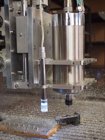
1. When it comes to zeroing out the X and Y position of the CNC at the beginning of a job, we have tried a number of approaches, including eye-balling (not very accurate), mechanical edge finders (don’t like these), and even a laser edge finder (not as accurate and cool as you’d think). For our solution, we installed a super-cool USB camera microscope from our friends at Adafruit onto the frame of our spindle. We mounted the camera using a small aluminum bracket that we designed in SolidWorks and machined on our CNC. We secure the camera bracket to the spindle frame using a 4-40 threaded hole that we tapped for that purpose. The microscope camera points downward toward the raw material. It displays a large, magnified image on the computer screen, including crosshairs. When we want to set the X and Y zero point, we turn on the camera and then move the spindle until the crosshairs line up exactly with the corner of the raw material (or whatever position we want to identify as the zero point). Because it’s a microscope, it’s very precise. We then press the Mach3 “REF ALL HOME” button, which we’ve re-purposed and re-programmed to set the X=0 and Y=0 based on the offset distance between the camera crosshairs and the spindle position. This allows us to quickly and easily zero out the X and Y axis to the exact point we need to.
The microscope camera is the tall, tube-shape thing clamped to the edge of the spindle mount. It has a built-in ring of LED lights to illuminate the subject area.
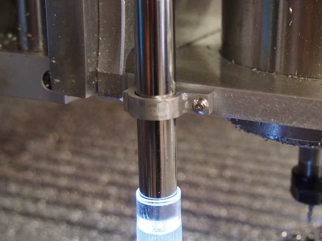
Close-up of the custom bracket we made to hold the tube-shpaed camera to the spindle frame
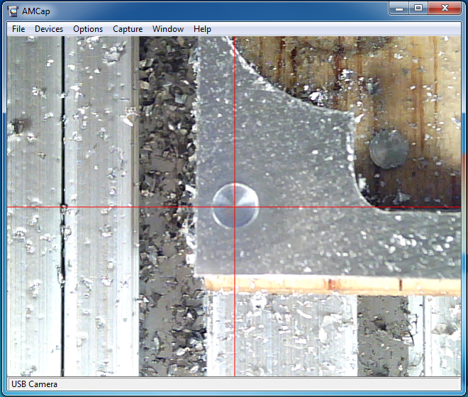
In this situation, we are using the crosshairs of the microscope to zero the CNC to the center of a small hole. The macro will set this as X=0, Y=0.
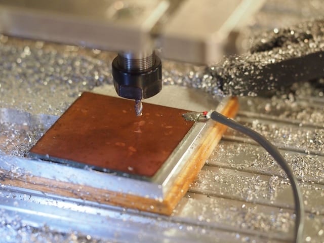
2. The Z-axis, which is the vertical position of the spindle, is by far the most important axis to zero out properly. For this, we rigged up a very cool solution that works great. We cut a piece of copper-clad circuit board (about 1″ x 1″) and soldered it to a long wire that we ran back to one of the 5 volt inputs on our controller. We ran another wire from the base of the CNC. These two wires, combined with the CNC and the end mill (which are both conductive), become like the leads of a voltmeter that is setup to test conductivity. We then wrote a macro in the BASIC language that runs when we press the “Auto Zero Tool” button on the Mach3 interface. When we want to zero-out the z-axis, we place the copper plate on the top of the raw material and press the button. The CNC moves the spindle slowly down toward the plate. The instant the tip of the end mill touches the copper plate the electrical circuit is closed. The macro instantly stops the spindle, sets the Z-axis zero point (by subtracting the .063″ thickness of the plate), and then moves up .125″ so that the copper plate can be removed. The whole process only takes a few seconds to complete. And the result is that the CNC determines exactly where the top surface of the material is and sets it as Z = 0.
The zero plate is placed on top of the raw material. The macro automatically moves the spindle down until the end mill touches the plate and closes the electrical circuit, which signals the CNC to zero the z-axis. Note the wire soldered to the copper plate.
These two techniques have really helped improve our setup time and accuracy.
We have been working on Aluminalis, our mechanical sixteen-legged walking robot. We’ve completed the initial build of the left side, which includes eight of the legs. Aluminalis is made with a complex assembly of custom linkages, segments, and shafts that we have been making in our machine shop. A single motor drives all eight of the legs (on this side) via a crankshaft that drives each pair of legs 90-degree out of phase with the other three pairs. That way, one pair of legs will always be on the ground no matter how fast the robot is moving. In the video below, we are testing the kinetic motion and gait of the left side.