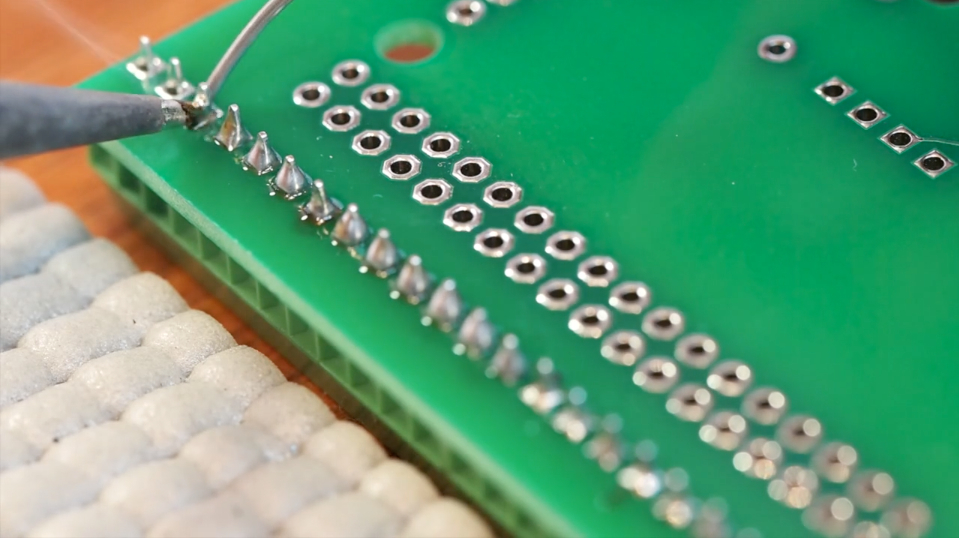
We are in the process of upgrading the first Mars Rover that we built for the New York Hall of Science. The goal is to upgrade its electronics so that the museum’s two rovers are identical and interchangeable. Here is a very brief video of Genevieve soldering the “Mars Rover Shield” that we designed. The shield, which is a complex circuit board that fits on top of an Arduino Mega, has 165-solder points, but the video is just a short clip that only shows her doing a few of them. She moves pretty fast, so she can complete a circuit board quite quickly. We used a macro lens on this video to see how close we could get. We like how we can see the solder melting and then solidifying around the pins as she does them. I chose this particular music because that was the music we were listening to when she was doing the work. I thought the lyrics fit pretty nicely: “Because I’m doing this for the thrill of it, killin’ it…”
Here at Beatty Robotics, we have a keen interest in mixing cool, old technology with exciting new technology. Recently, we became interested in Morse Code and telegraph equipment. We began exchanging written secret messages in Morse Code. And then we continued on by learning to tap the codes with rocks and listen to them at some distance. We are still learning and practicing, but it’s pretty clear that they are getting better and better and will soon be fluent. So now we’ve embarked on our next project, which is to build a functioning telegraph system by refurbishing several very old, antique telegraph keys and sounders, and then combining then with our modern electronics knowledge. We aren’t ready to show the completed project quite yet, but here are some pics of us wiring up the electronics. As we complete the project over the next few weeks, we’ll post pictures of the complete telegraph system (we’re hoping it’s going to look pretty cool), an explanation of how it all works, and the list of components.
Genevieve solders the headers on the Arduino Nano while I wire up the screw terminal board
I power up our wireless Xbee LCD screen to see if test messages are being transmitted properly from the Telegraph key. (The telegraph system itself won’t include an LCD screen. This was just for a test.)
Working together on some delicate soldering on the main microcontroller
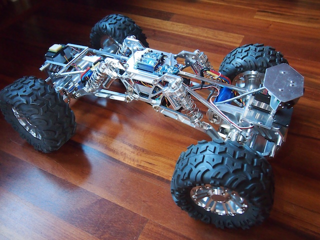
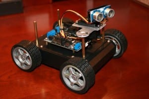
Today, we would like to introduce Terrabot, our Terrain Traveling Robot. Based on a modified “rock crawler” chassis, its primary purpose is to traverse rocks, branches, steep slopes, flower beds, boulders, mountain trails, and other extremely rough terrain.
Terrabot
Terrabot is equipped with 4-wheel steering (4WS). Two high torque servos shift machined aluminum linkages to rotate its front and back wheels independently. Note the navigation GPS on top of the back servo (on the left) and the sensor turret on the front (right). Terrabot’s four wheels are driven by two powerful brushless motors (bright blue) and robust gearboxes (centered in each axle).
Terrabot’s highly-articulated chassis is designed to twist up to 90 degrees as the robot is moving, allowing it to climb over huge boulders and other obstacles. In this picture, the chassis is articulated 45 degrees. Note that the back tires are still on the ground because the center linkages of the bot are twisted.
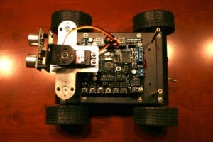
Terrabot’s topside electronics include a tiny Arduino Nano (lower left), an XBee Radio (right), and a 9-DOF Mongoose Inerntial Measurement Unit (IMU). The IMU measures the degree of tilt and the rate of acceleration in the X, Y, Z planes, which we plan to use for our stabilization algorithm.
Terrabot’s other electronics are stuffed into the little chamber inside the aluminum core (note the blue LED at the bottom of the picture). This includes the two Electronic Speed Controllers for the motors, the Pololu Maeastro motor/servo controller, the power rails, various voltage regulators, and other electronics. The navigation GPS (see the first picture), is mounted on top of the rear servo so that it has a clear view of the sky.
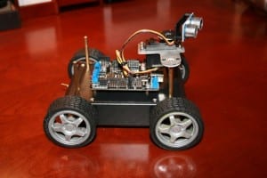
Terrabot Side View, showing the shocks, the frame, and LIPO battery beneath. Note the “roll posts” we installed on the top to protect the topside electronics if Terrabot falls off a rock during a climb and flips over. (We learned this one from experience!)
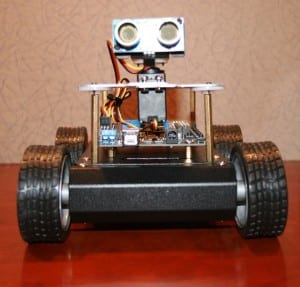
Terrabot Front View. There are three sonars mounted in the sensor turret, which rotates 270 degrees when the robot “looks around” to determine the best course through obstacle-ridden rough terrain.
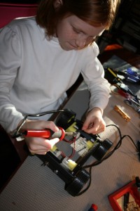
We have had a number of friends and family members ask how they can get started in robotics. They are interested in building a robot, especially a vehicle of some sort, but they don’t know where to begin. So, we have been working on the design for a small, inexpensive, easy to build, multifunctional, Arduino-based, programmable robot that will require basic robot building skills, but nothing too fancy. We call it “KitBot.” Our hope is to be able to help people get started. It will be able to function autonomously, but also by RC. It will include many off-the-shelf parts, a basic rover design, motors, servo, sonar sensor, sound, LED lights, and so on. These are our first pictures, which show the beginnings of the initial test project. It’s not done yet, but you can see the direction we’re moving. We have also sent all the parts to build a KitBot to a father and son team to be our initial Guinea Pigs (they wanted to try building it for a school project). As we work on refining the design and features, we’ll see how the father-and-son team does with the initial construction.
Soldering the power wires to the KitBot’s motorsAssembling our KitBot chassisKitBot: Top ViewKitBot: Corner ViewKitBot: Front ViewKitBot: Side View
Over the weekend, we built a small Power Distribution Unit for a new robot. We hacked a male Deans connector (which will plug into a high-amp LIPO battery), then soldered it into a marine toggle switch, then screwed it into a device of our own creation. We constructed a miniature power strip with screw terminals to power the various 12 volt electronic components of the robot, such as the motors, Arduino board, IMU, and others. We built it by soldering 8 individual screw terminal pairs to a tiny circuit board that we cut to be just big enough to fit them (about 1.6″ x 0.6″). Then we soldered all the pins on each side together so that voltage will flow down one line and ground will flow down the other. You can see in the picture that we have one small electronic component connected so far. In the past, we’ve just soldered all our power wires together into a big hunk of solder and then heat shrunk the whole thing, but using that approach made it difficult to add new components later on. We think this screw terminal idea will be more flexible by allowing us to add, subtract, and swap components as required.
I don’t understand why some company doesn’t already make a small Power Distribution Unit like this. We aren’t the only ones who need to distribute power to various components. I’ve looked and looked but can’t find anything that’s even close (i.e. small), which is why we decided to build this one ourselves. If anyone has any better suggestions, or has a source for small terminal strips for distributing power, please let us know.
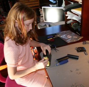
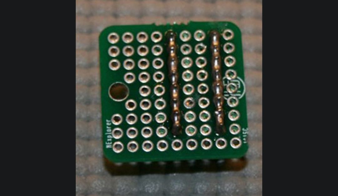
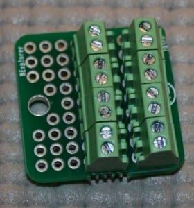
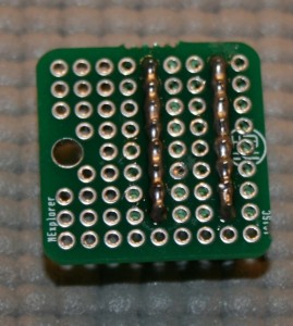
We also built a second screw terminal strip that was even smaller (1″ x 0.6″) for powering up to 8 lower current devices, such as the various 5 volt electronic components. See the pictures of the small green device below, with views of the top and bottom. When we did the soldering, I asked Genevieve to create two long caterpillars of solder along the row of pins. I think she did a very good job.
Building a couple of PDUs is a humble beginning, but every robot has to start someplace. 🙂
Genevieve building Power Distribution Unit
Our homemade mini Power Distribution Unit
Top Side View of our mini low-amp Power Distribution Unit
Underside view of the mini PDU showing Genevieve’s soldered “Caterpillars”