by Camille | Workshop Blog
Sometimes there are situations where it’s useful to control a GoPro by wired remote control and/or to integrate a GoPro into a DIY electronic project. This seems like it should be straight forward, but it’s not. I searched for a third party cable or module to plug into one of the GoPro’s ports, but as far as I can tell, there is nothing readily suitable on the market. So, in this post I describe how we hacked into a GoPro Hero 4 Black in order to integrate it into a robot we’re building.
First, we tried communicating through the Hero Port (the large port on the back of the camera). This seemed very promising. You can do some neat things with this port. But unfortunately, controlling the GoPro’s shutter button isn’t readily feasible because GoPro didn’t set it up as a simple digital pin. Instead, they created a proprietary communication protocol that they purposely do not publish. They don’t want people to hack into their cameras. Next we tried using the USB port, to no avail. Then we tried hacking into the wireless remote control, which we were able to do pretty easily, and it sort of worked, but it did not provide the speed and reliability we needed. So, in the end we went old school. We tore the GoPro apart, hacked into the case, and soldered wires to the button rings. It isn’t pretty or elegant, but it works. Here are the details of what we did:
1. First, we needed to integrate the GoPro’s power into our robot. We didn’t want to have a separate battery. So we removed the battery completely, plugged a mini USB cable into the USB port on the side of the GoPro, and hacked the other end. The Hero 4 will run entirely off a USB cable with no battery in it. If you cut open a USB cable, you’ll see four or five wires. Normally the red is positive voltage and the black is ground. If you don’t see a red and black, then Google USB wire color codes for further clues. We connected the red wire to the robot’s 5v regulated power rail. So now, when the robot has power, the GoPro has power. When the robot goes off, the GoPro goes off. Another option is to use a Switronix Battery Eliminator, if you would prefer to use the GoPro’s Hero Port.
2. Second, we needed to turn on and control the GoPro from the robot, specifically from an Arduino micorcontroller. Note: A GoPro does not turn on just because it has electrical power. In order to operate the camera, you need to press the Power/Mode button (on the front) and the Shutter/Select Button (on the top). The following instructions voids your warranty, causes irreversible damage to certain parts, and has an extremely high potential of turning your $500 GoPro into a mess of useless bits of metal, plastic, and electronics. Welcome to DIY hacking!
A. Use your fingernail or a prying tool to remove the front facade. It’s stuck down with adhesive and two little plastic clips on each of the four sides. This takes time and patience. The front plate is thin aluminum. Unless you’re very careful, you’ll end up bending it. You will probably be wanting to put the plate back in place when you’re all done, so be careful.
B. Next, use a small electronics screw driver to unscrew four screws to loosen the electronics.
C. Separate the case from the electronics at the port end first, carefully prying and wiggling until you are able to pull out the electronics. Again, this will take time and patience. Be careful.
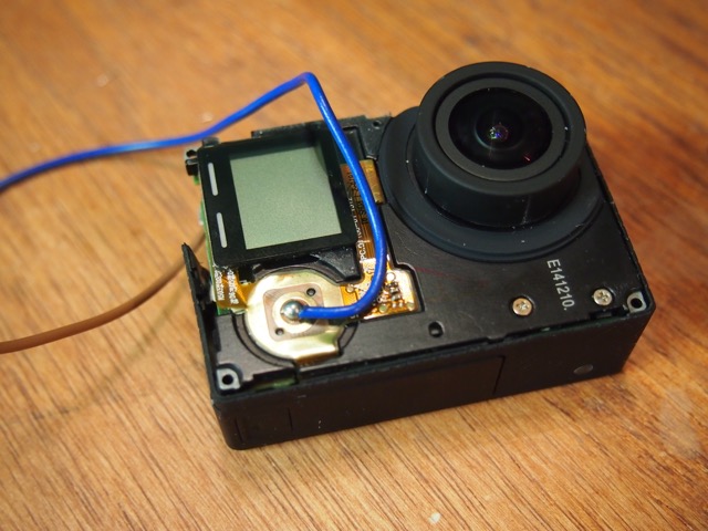
D. As the electronics come out, you’ll see there are two main sub-assemblies connected by a thin, delicate orange flat ribbon. Try to keep the sub-assemblies together. If you fail at this, you’ll pull out the ribbon connector. It’s a major pain and risk to put that tiny thing back into place. However, it is doable. It took twenty minutes of fussing, but we managed to do it.
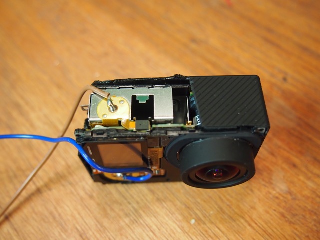
E. Use big snippers and other tools to cut away the top part of the case to expose the Shutter/Select button on the top. I wish there was a better way, but we could not find one.
F. Use your fingernail to scrape off the little white touch area beneath the Shutter/Selection Button.. Solder a wire to the tiny central circle (be very careful not to connect the outer circle to the inner circle). Run the wire to a relay controlled by your Arduino. Use the relay to close the circuit to ground using a digitalWrite command.
G. Do the same thing on the Power/Mode Button, which is on the front of the camera.
H. Replace the case and physically integrate the camera into your project. In our situation, we have machined a special aluminum case that we designed specifically to meet the needs of our particular project. When it’s all done, the mangled plastic GoPro case will not be visible in any way.
After doing the steps above, we now have two wires coming out of our GoPro. We’ll attach each wire to a little relay module, which in turn we will control with two digital pins on our Arduino. We’ll then use simple digitalWrite commands to operate the two relays, giving us complete control of the GoPro.
In the next post, I’ll provide some photos and explanation of the new case we machined for our wired GoPro. In the post after that, I’ll describe how we are using the GoPro on the robot to wirelessly stream HD 1080p/60 video to a monitor and a HD Goggles.
by Camille | Gallery, Robots, Slider, Workshop Blog
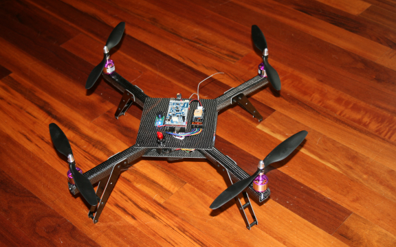
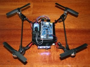
Today, we would like to introduce Black Dragon, our newest flying robot quadrotor. This newest flyer incorporates everything we’ve learned to date about ease-of-use, modular maintainability, crash resistance, lightness, and safety. While we constructed all our previous full-sized quadrotors with aluminum, we designed and built this new flyer with super-cool carbon fiber material. This particular type of carbon fiber, which carries the brand-name “Dragon Plate” (www.dragonplate.com), is used in the aerospace and defense industry, among others. It’s very light, very strong, looks fantastic (the photos don’t do it justice), and is surprisingly machinable.

BLACK DRAGON: Our first carbon fiber quadrotor

Our CAD drawing for the Black Dragon frame design

Our Carbon Fiber Frame

Carbon Fiber Arm. Note that we drilled the motor holes and landing gear holes directly into the arm in order to reduce parts
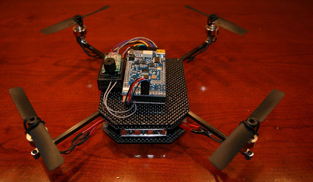
Like our previous quadrotors, we are using the Arduino-based ArduPilot Mega board as the main controller, a 3-axis Inertial Measurement Unit shield (IMU), a GPS for autopilot navigation, Magnetometer for heading control, and a Sonar for altitude control. The robot can be flown via an RC controller or on various autopilot modes. New features include a large illuminated toggle switch for easy on/off in the field, large main plates to hold electronics and wires, improved frame design, complete elimination of the motor mounts (which used to be susceptible to bending), an x-oriented frame (as opposed to +) to provide an open field of view for a camera mounted on the the front, and improved landing gear.
The carbon fiber material is excellent. We love it. It’s easier to machine and work with than we expected (even with the necessary safety precautions), it’s very attractive, but best of all it’s both very light and very strong. For example, the previous aluminum arms weighed in at about 50 grams each. The new arms are 21 grams each. The whole unit ways in at about 850 grams without the LIPO battery.

Close up view of some of Black Dragon’s electronics
We’ve loaded the software into the microcontroller, calibrated the ESC/motors, double-checked the prop rotation, tested the sonar, set the magnetic declination on the magnetometer, confirmed the GPS is giving good long/lat, and it’s ready to fly. We’ve flown it a few inches off the floor indoors just to make sure it’s good-to-go and so far it seems excellent. Perhaps our best ever. As soon as the rain stops, we’ll be testing it in the big blue sky.
For more details on our various flying drone robots, go here.
I want to give special thanks to the folks at Dragon Plate for sending us their cool material.
by Camille | Workshop Blog
Today, we upgraded our little mini quad rotor flying drone that we call “The Black Hornet.”
We replaced his main board, installed new propellers, re-fixtured his motor mounts, and got him in good flying shape. He flew steady and strong in our test flights.

Genevieve soldering the main circuit board for the Black Hornet

Genevieve connecting electronics on the Black Hornet mini quad rotor

Genevieve finalizing the upgrades on the Black Hornet mini drone
The fully-upgraded Black Hornet mini drone
by Camille | Robots, Slider, Workshop Blog
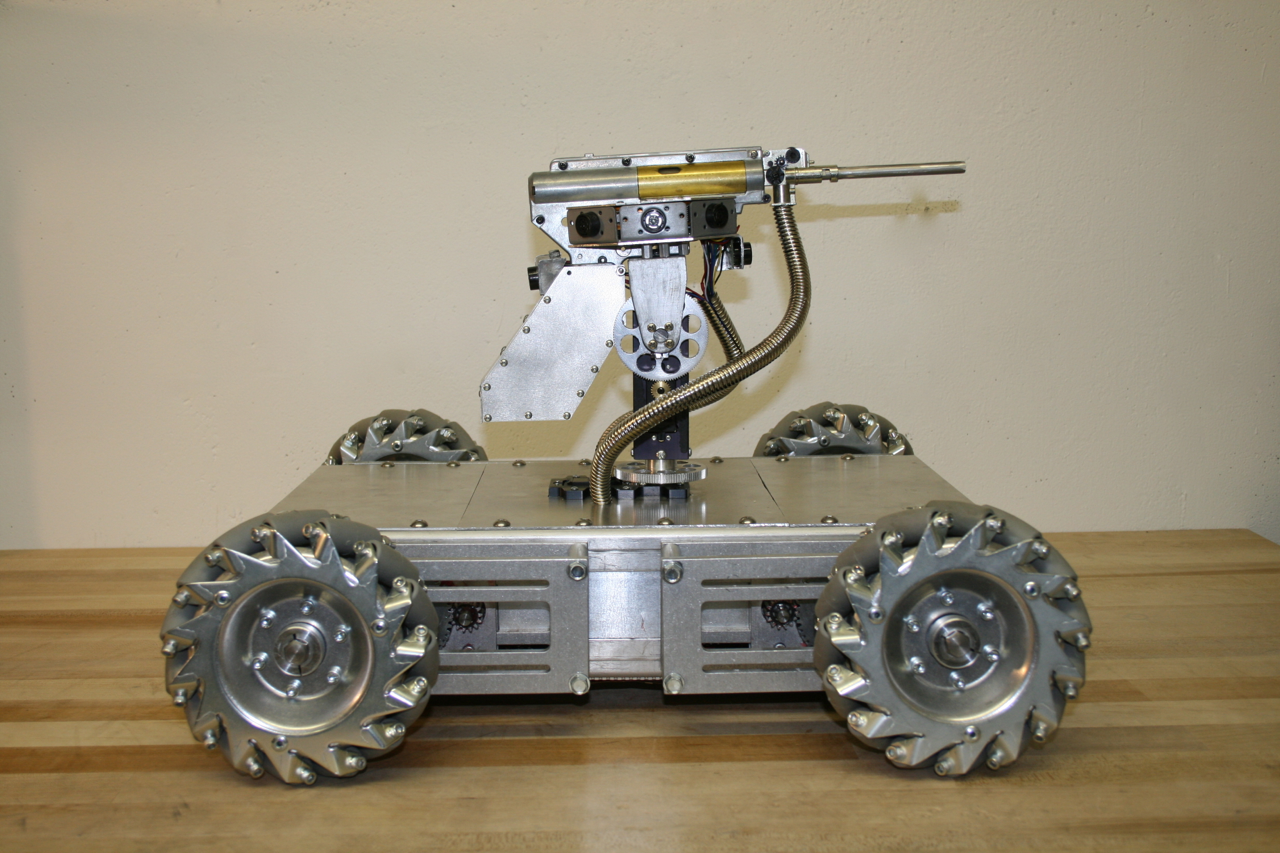
We would like to introduce Mechatron, our mechatronic tank. When we designed and built Mechatron we wanted him to be tough looking, industrial, and retro-futuristic, with lots of metal, rivets, and gears. He’s built entirely out of aluminum, brass, and steel, but inside, he’s chock-full of high tech electronics. See pictures and more text below. And be sure to watch the video to see Mechatron in action!

Mechatron includes special wheels with rollers slanted at 45 degree angles and driven by dedicated gearboxes, four powerful motors, and a software-controlled drive system that we wrote that operates each of the wheels independently. The result is that he can move in any direction at any time in any orientation. In other words, he can drive forward and backwards or turn like a normal vehicle, but he can also drive perpendicular to the direction he’s facing or at any desired angle. Weighing in at forty five pounds, he is by far our heaviest robot, but he is also our most agile, which makes him tremendous fun to drive.
Mechatron’s gun turret pans 360 degrees, includes 8 range-finding sonars for target detection, a laser, and a high-powered electric automatic weapon that shoots brass or plastic pellets. Ammunition is fed from the base of the robot up through one of the articulated metal tubes attached to the turret (the other tube contains wires). He can fire extremely rapidly while standing still or moving.
Strips of 52 programmable RGB LED lights have been mounted on Mechatron’s underside and within his turret. The turret LEDs indicate the robot’s current mode and whether the weapon system is armed. The LEDs on the underside change color depending on the direction of each of the individual wheels (Blue = Stopped. Green = Forward. Red = Backward), which helps to illuminate how Mechatron’s unique drive system works.
Mechatron is designed to function in a variety of different modes, including both user-controlled Radio Control and/or fully-autonomous. For the RC mode, we built our own controller which matches Mechatron in look-and-feel. The left joystick controls the pan and tilt of the gun turret and includes the firing button on top (which is armed using the missile switch). The right joystick controls the drive system. Forward and Backward motion (Y-axis) moves the robot forward or backward. Twisting the joystick turns the robot in the direction of twist (Z-axis). Moving the joystick left or right (X-axis) causes the robot to strafe left or right while maintaining his current orientation. Combined X-Y-Z joystick motions create unique and agile movements, such as strafing in circles. The robot can move in any direction, while panning and tilting its turret and firing all at the same time.
Technical Specifics:
- Overall Design: Beatty Robotics
- Arduino Software: Beatty Robotics
- Metal armor plates: Beatty Robotics
- Main Microcontroller: Arduino Mega 2560
- Microcontroller used for controlling LED lights: Arduino Nano
- Light Controller Software: Beatty Robotics
- Wheels: AndyMark (special thanks to Andy Baker, who was great to work with on these)
- Drive Gears: Modulox (special thanks to Dan Richardson at iR3 Creative Engineering & Andy Baker at AndyMark)
- Pan-Tilt gears and other parts: RobotZone (special thanks to ServoCity)
- Pan-Tilt Servos: Hitec Digital
- Sonars: (12) Maxbotix MaxSonar Ultrasonic Sensors
- Turret Sensor Head: Beatty Robotics
- RGB LED strips: Adafruit (Go Blinky Belt!)
- MP3 Sound Board: Sparkfun MP3 Trigger
- Servo Controller: Pololu Maestro
- Voltage Regulators: Pololu & Dimension Engineering
- High-amp Relays: DFRobot
- Motor Controllers: (2) Dimension Engineering Sabertooth 2×25
- Motors: (4) CIM
- Wireless Communication: Xbee Radio with Sparkfun Xbee Explorer Regulated board
- Joy Sticks: (2) 3-axis hall-effect joysticks from CH Products
- Batteries: (1) 12v 3-cell Lithium-Polymer 20C
- Aluminum, hardware, fasteners, wire, tools, and much else: McMaster-Carr
- Wire, electronic components, IC boards, and much else: Sparkfun & RobotShop

by Camille | Workshop Blog
We have been hard at work on our latest project called Mechatron. To control our Mechatron robot as well as our Mars Rover, we designed and built our own remote control box. We developed our own communication protocol for transmitting commands from the remote control to the robot. On other projects we used iPhones and Playstation remote controllers, but in this case we wanted to build a large, metal box with lots of retro-switches and joysticks.

Remote Control Box for our Mechatron Robot
Inside wiring for the Mechatron Remote Control
Technical Details
- Microcontroller: Arduino Mega 2560
- Remote Control Software: Beatty Robotics
- Design and Construction: Beatty Robotics
- Box: Aluminum sheet and metal screws
- Radio: xBee Radio module
- Joysticks: Digikey x-y-z-axis, hall-effect, 1 button joysticks
- Rotary LED Encoder Ring: Mayhew Labs
- Battery: 12v LIPO
Notes:
1. Although it wasn’t cheap, the hall-effect 3-axis joystick was critical for controlling the function of Mechatron’s specialized drive system. We originally tried a traditional analog/resistive/potentiometer-style joystick and it did not work well at all. We thought our whole project was going to fail until we realized that not all joysticks are created equal. The joystick based on the “hall-effect” principle worked perfectly for us.
2. You can’t see it in these photos, but this controller can be charged via banana jacks and re-programmed via a USB jack without having to unscrew and remove the case. The same is true for the Mechatron robot itself.

