Today, we would like to introduce Terrabot, our Terrain Traveling Robot. Based on a modified “rock crawler” chassis, its primary purpose is to traverse rocks, branches, steep slopes, flower beds, boulders, mountain trails, and other extremely rough terrain.
Terrabot
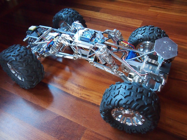
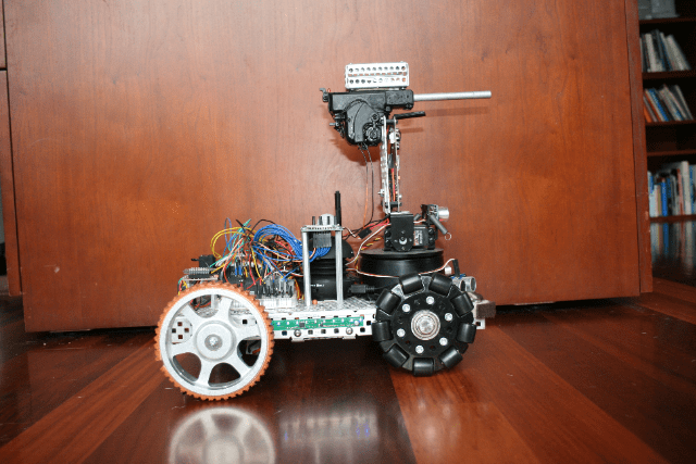
Terrabot is equipped with 4-wheel steering (4WS). Two high torque servos shift machined aluminum linkages to rotate its front and back wheels independently. Note the navigation GPS on top of the back servo (on the left) and the sensor turret on the front (right). Terrabot’s four wheels are driven by two powerful brushless motors (bright blue) and robust gearboxes (centered in each axle).
Terrabot’s highly-articulated chassis is designed to twist up to 90 degrees as the robot is moving, allowing it to climb over huge boulders and other obstacles. In this picture, the chassis is articulated 45 degrees. Note that the back tires are still on the ground because the center linkages of the bot are twisted.
Terrabot’s topside electronics include a tiny Arduino Nano (lower left), an XBee Radio (right), and a 9-DOF Mongoose Inerntial Measurement Unit (IMU). The IMU measures the degree of tilt and the rate of acceleration in the X, Y, Z planes, which we plan to use for our stabilization algorithm.
Terrabot’s other electronics are stuffed into the little chamber inside the aluminum core (note the blue LED at the bottom of the picture). This includes the two Electronic Speed Controllers for the motors, the Pololu Maeastro motor/servo controller, the power rails, various voltage regulators, and other electronics. The navigation GPS (see the first picture), is mounted on top of the rear servo so that it has a clear view of the sky.
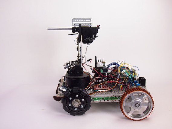
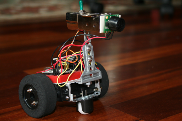
Terrabot Side View, showing the shocks, the frame, and LIPO battery beneath. Note the “roll posts” we installed on the top to protect the topside electronics if Terrabot falls off a rock during a climb and flips over. (We learned this one from experience!)
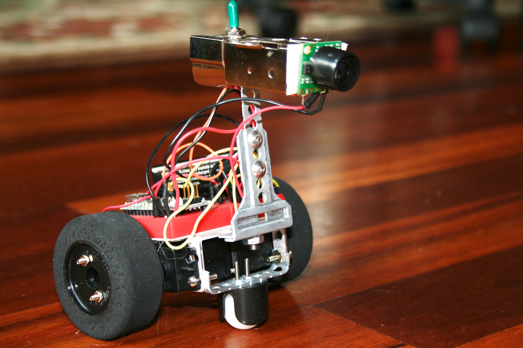
Terrabot Front View. There are three sonars mounted in the sensor turret, which rotates 270 degrees when the robot “looks around” to determine the best course through obstacle-ridden rough terrain.
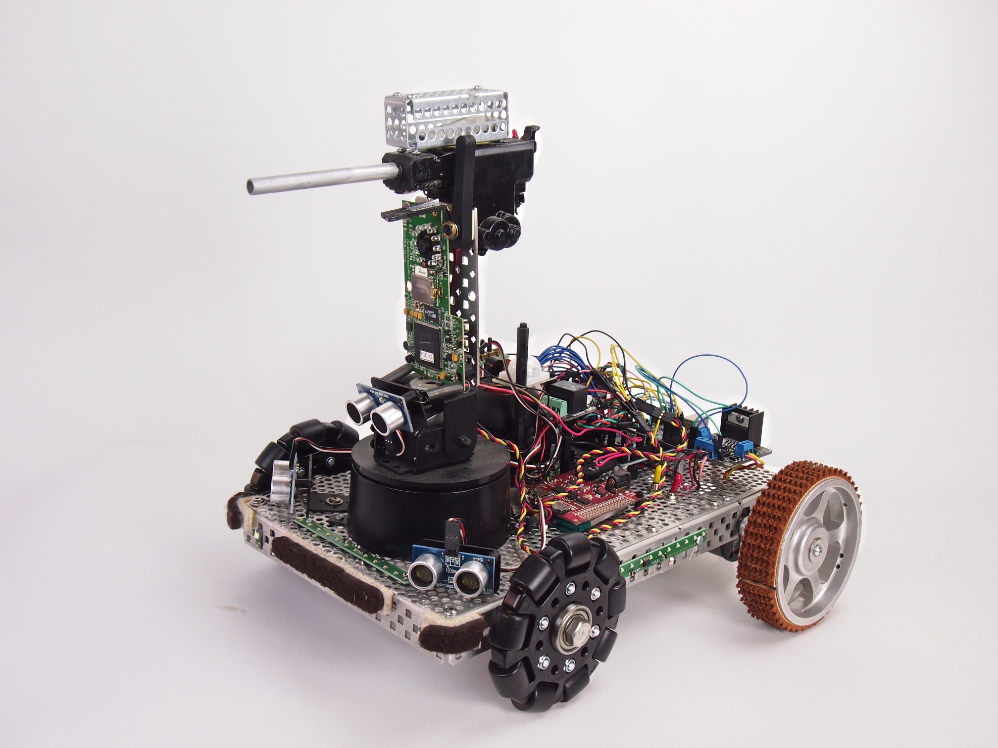
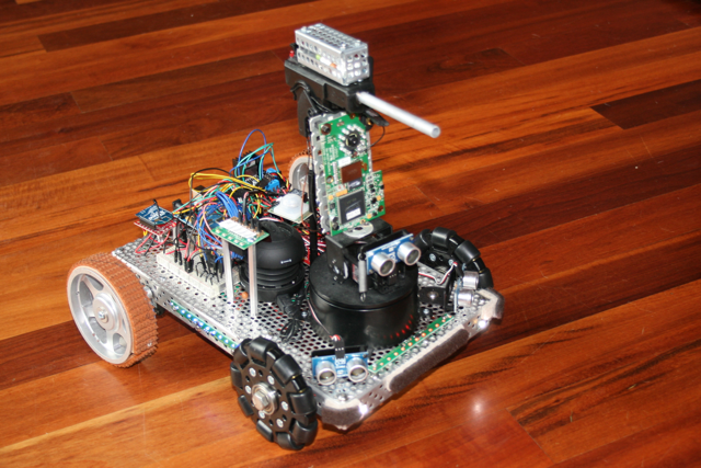
Security V is a small security robot. It’s equipped with the following capabilities:
Automatic electric gun (Airsoft pellet gun) with ammunition cage
Pan-Tilt Gun Turret
Targeting laser
FPV Camera
(3) Ping sensors for object avoidance
LED Light Strips
MP3 Sound Player
IR Human Detection Sensor
Moto Controller
Two motors
Two treaded drive wheels and two omni wheels
Arduino Mega Microcontroller
Xbee Radio for remote control
Button panel for selecting the mode
We programmed it with five different modes:
1. Roams autonomously around the house, playing R2-D2 like sounds as it explores & avoids obstacles 2. Remote Control 3. Dance Mode (Plays the song Mr. Roboto and dances around) 4. Guard Mode (enables its infrared human detection sensor and plays a police siren if anyone tries to sneak past it) 5. Shoot (shoots the gun)
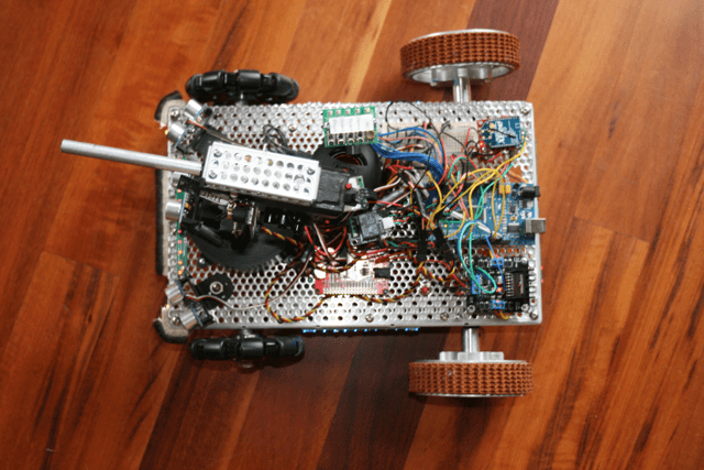
Security RobotSecurity RobotSecurity Robot – Top View
After building a number of indoor robots, we decided to build an outdoor robot capable of traveling through rough terrain. We call it “Trekker.”
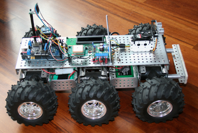
TREKKER ROBOT. Six wheels. Six motors. Batteries below deck. Electronics above deck.
First, we put together a six-wheel independent suspension with a separate motor on each wheel and large knobby tires. Each wheel moves up and down separately, which allows this little beast to climb up and over just about any obstacle (rocks, slopes, cats, whatever gets in its way). Here is a video of Trekker going over a large pile of books.
This is by far our funnest robot to drive via Remote Control, but this true magic of Trekker is his navigational capabilities.
We wired Trekker with a GPS chip and a tilt-compensated magnetometer (an electronic compass that works even when the robot is tilted). When Trekker first comes on, he automatically looks for and synchs with as many satellites as he can find in the sky (usually about 10-15). We programmed Trekker to determine his exact latitude and longitude position using the GPS as well as his directional orientation using the magnetometer. He then travels on his own to a series of latitude and longitude waypoints (that we get from Google Earth). Trekker’s navigational algorithm was one of our most ambitious software challenges to date. Our favorite test run is to put him in our backyard and give him instructions to drive around the big tree, down to the barn, drive around the goat pen, and return to us. He does it beautifully, all on his own, moving systematically from one waypoint to another. We also equipped him with a forward-facing sonar, which swivels back and forth on a pan servo, to avoid trees and other large obstacles along the way.
Trekker Robot – Top View – The white square in the middle is the GPS, which is used for navigation. When traveling between waypoints, the Longitude and Latitude display on the little LCD screen.
Trekker – Front View – This provides a nice view of the sonar at the front of the robot, which is used for obstacle detection and avoidance when traveling in automated mode. The magnetometer (compass) is mounted on a tall shaft at the back of the robot to keep it clear of interference from the other electronics, especially the radio.
This picture of Trekker’s underside shows how each wheel connects to a separate motor (black t-shaped things). Each motor housing is on springs and swivels so that it moves separately from the other motors.
Thanks to the shock-absorbing independent suspension of each of its six wheels, Trekker rolls over pretty much anything
Software Modes
We programmed Trekker with a several different modes he can operate in:
Navigate autonomously to a series of user-provided Longitude/Latitude Waypoints
Roam autonomously using swiveling front sensor to avoid obstacles and find best path
Radio Control (RC) – display commands and motor speeds on LCD
Radio Control (RC) – display longitude, latitude, and heading on LCD
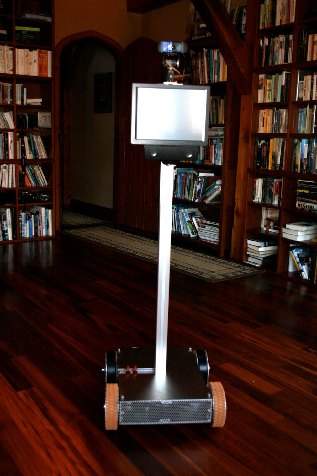
This is Telegance. He is a Telepresence Robot, which means he’s a driver-controlled mobile video conferencing system.
Imagine I’m out in the world. I can use my laptop or any other computer to link into the robot through the Internet. The people around the robot see my face on the robot’s screen. The sound of my voice comes through the speakers, which are mounted just below the screen. I hear through the robot’s microphone and I see through the robot’s camera, which is mounted on two little servos, so I can tilt and pan the camera where I wish to look. I can drive the robot around the house, to the kitchen or the bedroom or where ever, using the robot’s built in motors. His wheels are designed to drive or turn on carpet, tile, and hardwood floors.
Side View of Base
How We Built Him
Telegance was a lot of fun to build, but he was definitely one of our most challenging robots so far. We learned a lot. Telegance is our first robot that is based on a computer rather than a microcontroller chip/board. Our vision was to build a robot based on a Mac. So, we grabbed a Mac Mini, tore it apart, ripped everything off that we didn’t need, rewired it for DC (it was an AC computer), and replaced the conventional hard drive with a Solid State Drive (SSD) (so that we didn’t need a fan, it didn’t make any noise, and it used less power). We installed just the stripped down motherboard into the base of the robot. When it booted up it was silent, fast, and ran on 12 volts like the rest of the robot. We then connected this to an Arduino Mega microcontroller through a USB cable. The Mac Mini, which runs a special Skype plugin, handles the webcam videoconferencing (using Skype), the touch screen, and 802.11b networking. The Arduino handles the drive motors, the webcam pan-tilt servos, power distribution, and other robotic features. We constructed the robot’s frame in our workshop using raw aluminum plate and c-channel. We especially like the cool wheels on this robot.
Touchscreen, Webcam on Tilt-Pan Servos, and Speaker: Telegance Robot
Under the Hood: Mac Mini motherboard (left), Arduino Mega Microcontoller (right), Sabertooth Motor Controller, Xbee Radio
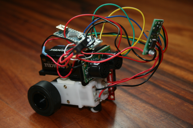
We made these tiny-bots from the small, spare parts of their older brothers. Though not as high-tech as the larger ones, these little guys defiantly beat the record of being the smallest by a long shot. Their size makes it easy to put them in boxes and bring them to school to share with my classmates and tell them a bit about breadboards and Arduinos, soldering and heatshrinks and all of the others. These robots include Sonar obstacle detection, roaming navigation, as well as Remote Control (RC).