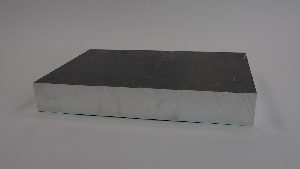
We’ve been working on a fun new robot we call Metalbot. Our goal was to build an autonomous rover with a unibody design that was machined out of a single block of metal. We started with this 13” x 9” x 1.75” block of 6061 aluminum:
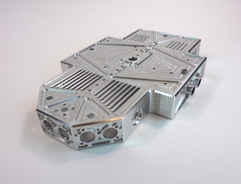
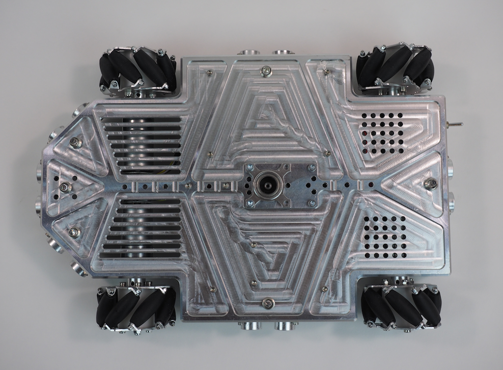
When the machining was done, the robot’s body looked like this. It’s a hollowed-out shell that is about 1/8” thick with holes, slots, and pockets for the motors, LEDs, sensors, and other electronics.
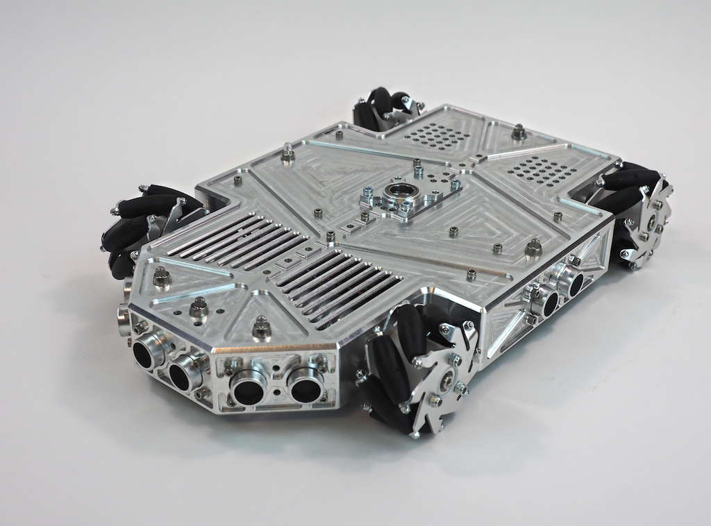
Once Metalbot was assembled with the internal components, it looked like this:
What do you think? We think it’s pretty cool looking. Do you like it?
Work-in-Process Pics
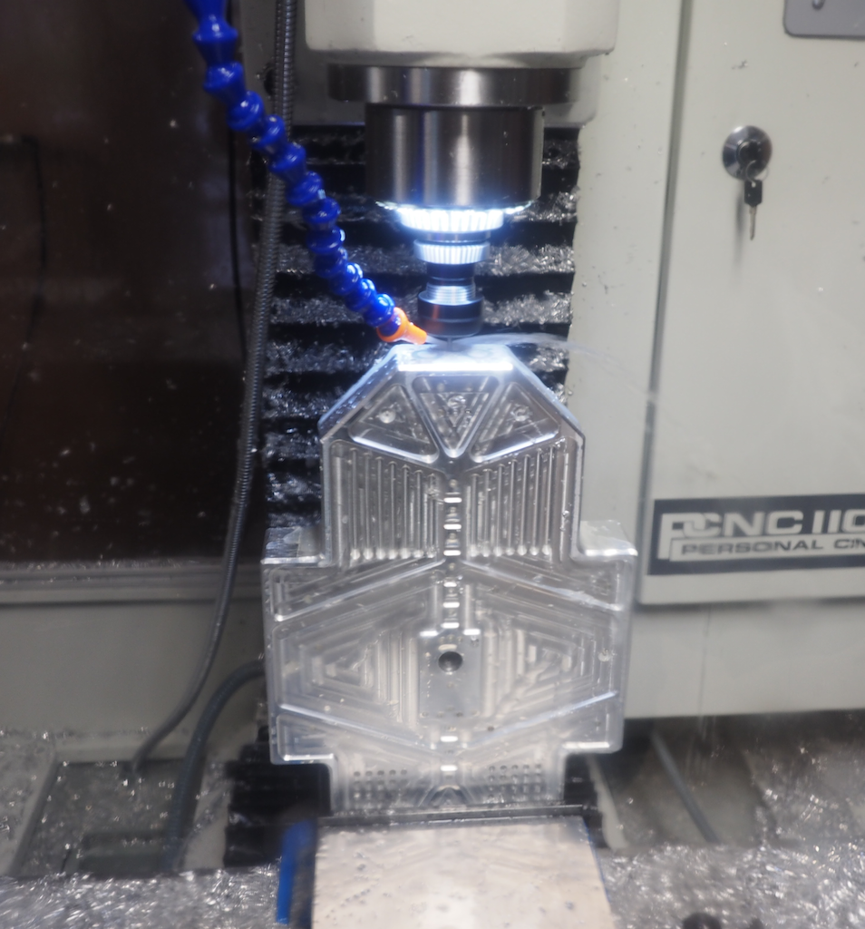
In this first picture (which was taken through the polycarbonate enclosure), we clamped the part vertically in the vise and we’re using an 1/8″ end mill to machine the detail on the front of the nose. In a previous operation we clamped the stock flat and machined the top of the robot, so that work is already done. Because this part has features on every side, machining it required us to clamp the stock in the vise in 8 different orientations: top, left side, right side, back, front, 45-degree left nose, 45-degree right nose, and bottom.
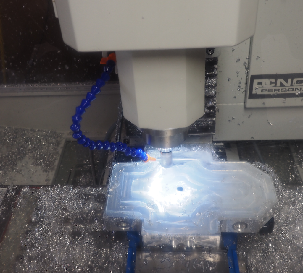
In this next picture, we’re on the last setup, machining out the large pocket on the underside of the robot. This turned the aluminum block into a 1/8” thick shell. The large pocket appears to be glowing because the ring of LEDs we installed around the mill’s spindle are shining into the coolant that has filled the pocket. We’re using a 25mm (.98”) modular end mill here, which is designed to remove material fast. Of course, there were a lot of metal chips, but it’s important to remember that aluminum is easy and efficient to recycle.
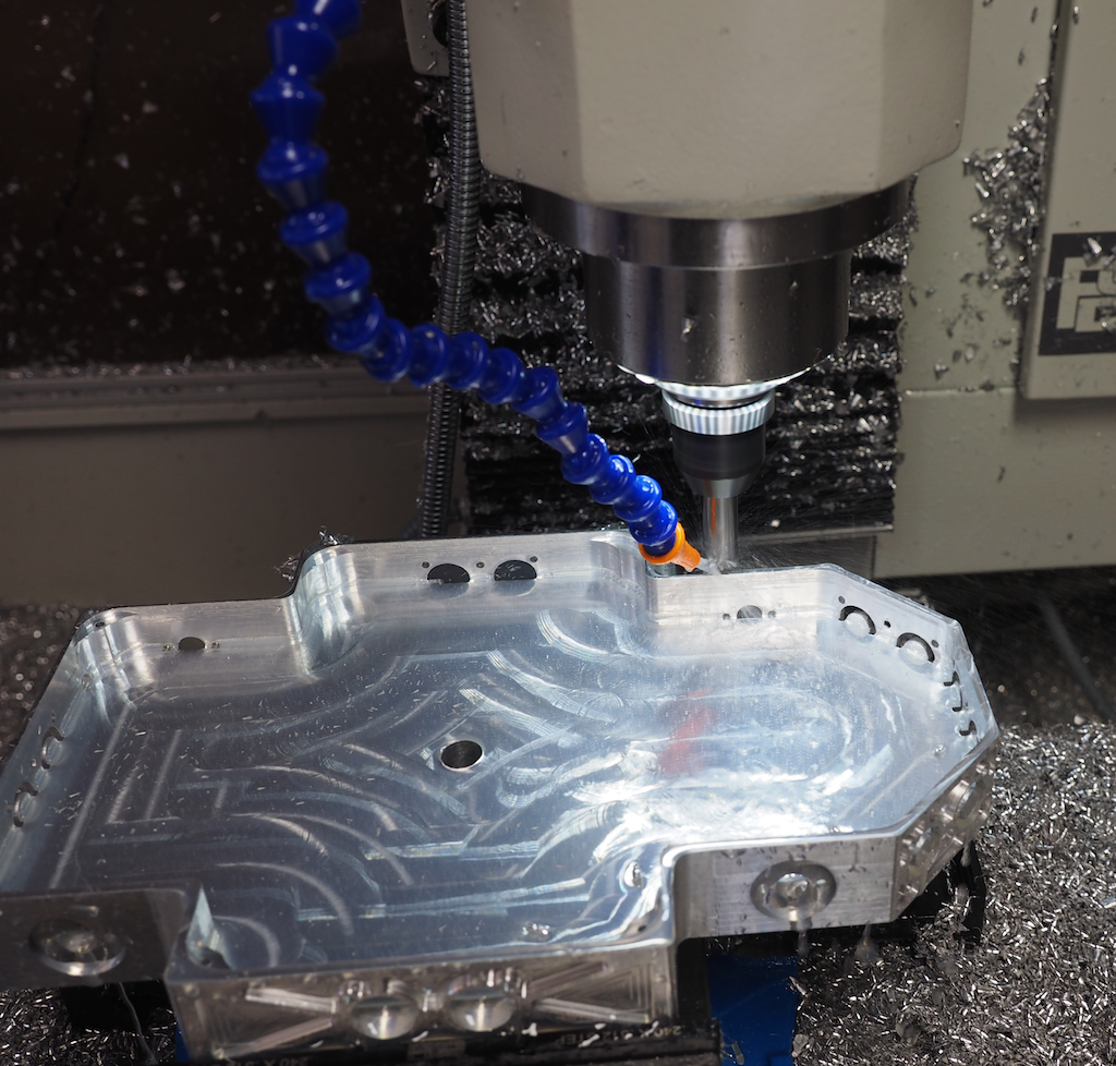
In this picture we’re half way done digging the pocket and we have the machine take a break from the hard work to chamfer the outside contour:
Once the body is machined, we screwed in the wheels, motors, and electronics, which are screwed upside down on the underside, where they are easy to access when the robot is turned over. We will install a bottom plate later.
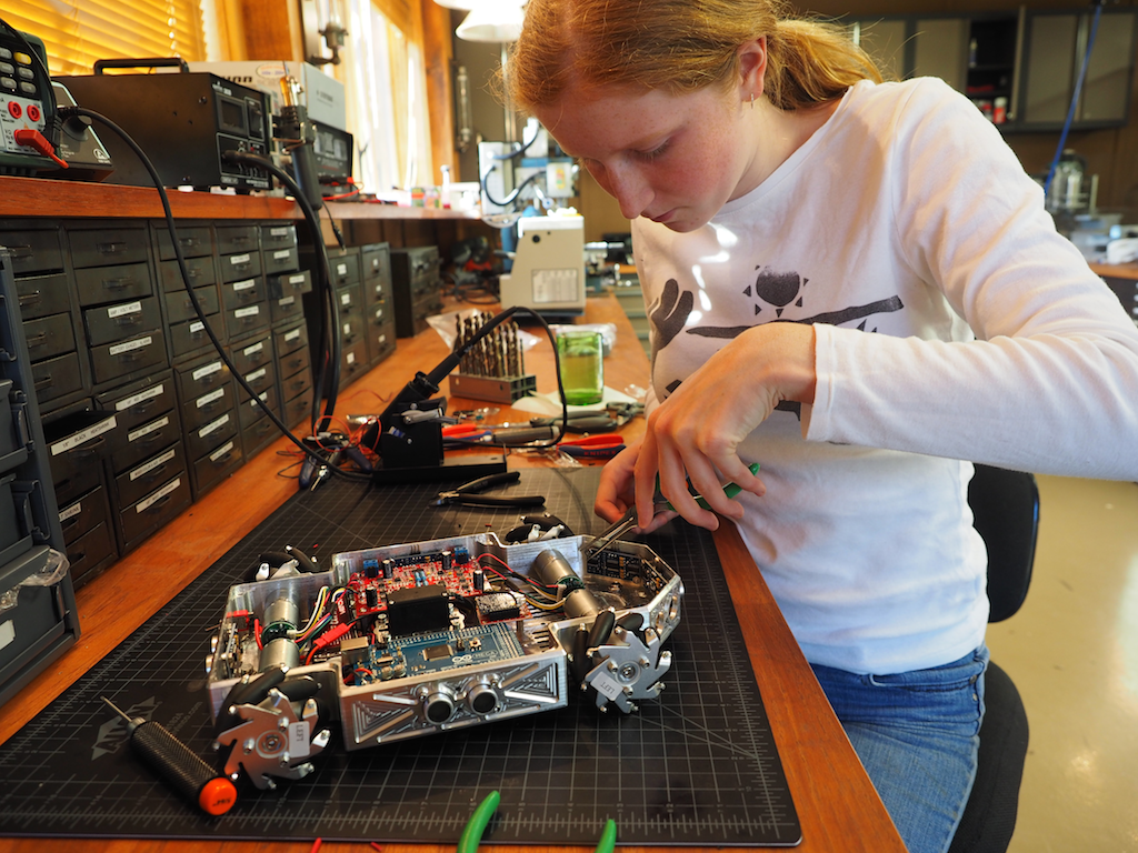
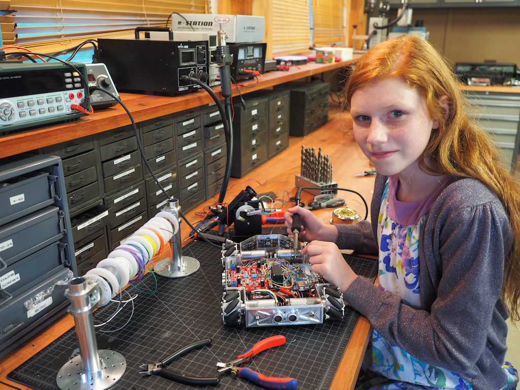
Then we did the wiring and soldering:
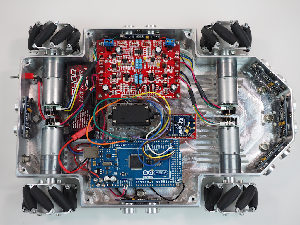
Here is the underside of the robot with most of the electronics installed. We’re using an Arduino Mega and a 4-channel Motor Controller, along with 4 Pololu gear motors to drive the mecanum wheels, which will allow the robot to strafe. The robot is also equipped with 6 Ping ultrasonic sensors for autonomous object detection, a LIPO battery, a main power switch, 6 NeoPixel RGB LEDs to indicate the state of each sensor, an Xbee Radio, and a panning servo (black thing in the middle). The robot will also be equipped with an MP3 module and speaker for sound, but those haven’t been installed yet.
The robot’s finished body is 8” wide and 12” long. The rover can be fitted with either the mecanum wheels shown or CNC-machined conventional wheels (not shown). Our original goal was just to machine a cool looking rover out of a single piece of metal, but as we went along, we decided to add some flexibility into the design for future enhancements in case we wanted to do more with it. The robot has been designed with a central spine of holes and ridges for attaching future add-ons, including a servo mounted in the center, which will support a pan-tilt turret for a camera, gun, or arm. We have designed the pan-tilt turret to utilize the Actobotics ecosystem, but other pan-tilt mechanisms could also be used. There are also holes on the front and rear of the top deck that are compatible with the full range of Actobotics components such as brackets, hubs, and channels, which really adds a lot of flexibility.
The next step is to work on the sensors and software programming. With its mecanum wheels, it should be able strafe like a champ very soon.
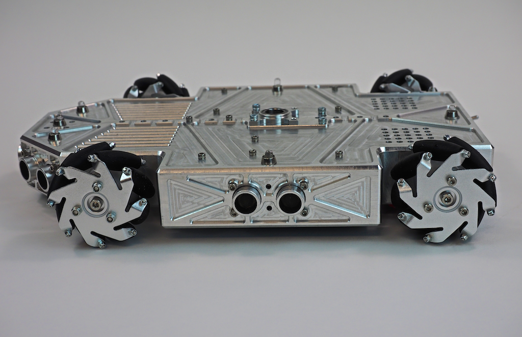
Here are a few more pictures of Metalbot so far. Let us know what you think. Do you like the overall design?
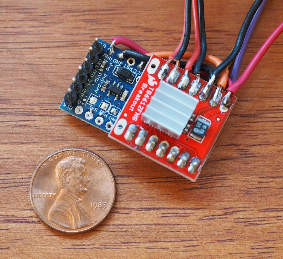
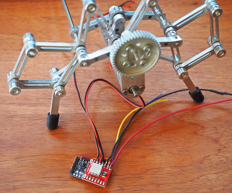
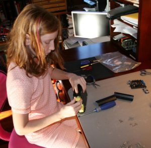
Recently, we encountered a situation where we needed a very small Arduino microcontroller and motor driver. On Alumini, our 12-legged walking robot, there won’t be an electronics box, so we will be integrating the electronics into the bones of the creature. Our goal was for the creature to appear to be all legs. So, we needed the electronics to be very small, hidden beneath and between the robot’s many leg linkages. After trying a few experiments with different components and approaches, we’re excited about the approach we came up with. We don’t know whether it’s going to work in the final robot yet, which is still under construction, but so far it seems promising. The Arduino Pro Mini board from Sparkfun is just 0.7″ x 1.3″ and it’s on a 0.032″ thick circuit board, so it’s a very small, thin little microcontroller indeed. We love the form factor. If it works on this project, it may just become our “go-to” microcontroller for small projects. We also decided to try Sparkfun’s tiny 1A Motor Driver, which is only .8″ x .8″ square.
Genevieve and I soldered up the boards and they’re working well so far, but the one negative we’ve encountered is that the motor driver is a very simple little thing. It’s basically just a breakout board for the TB661FNG chip, so it doesn’t have a lot of on-board smarts. Instead of a single TTL serial wire like we’re used to, it requires 2 PWM pins and 5 digital pins to control it. We don’t have a lot of room for wires, so we did something we thought was really cool: we sandwiched the boards together and turned the motor driver into a tiny make-shift shield for the Pro Mini board. We lined up the pins just right, wrote the software to correspond to those pins, and literally soldered the boards together, which eliminated the need for the 7 control wires. We thought there was a fair chance we would ruin the two boards, but it worked like a charm. In the photo, the seven solder points near the penny (on the red board) are the control pins between the arduino and the motor driver. The other wires (at the top of the photo) go to the 11.1V LIPO battery, motors, sonar sensors, xbee radio, and other components of the robot.
The next big question is whether this little motor driver, which is rated at 1.2A per channel can handle Alumini’s 20mm x 42mm metal gearmotors, which are rated for a free-run current of 0.25 Amp and a stall current of 3.3 amps. Normally we would use a 5A motor controller for these motors, but the 5A motor controller was too large to fit on Alumini’s delicate frame. Once we had soldered our mini robot control system together, we were able to do some testing. When we run the partially-completed Alumini robot on the bench, the motors are pulling .6 Amp each, but they don’t have much force on them yet. We’ll see how this goes once we get Alumini scuttling at high speed around the room. We may end up smoking the motor driver and going back to the drawing board. We thermal-pasted a tiny aluminum heat fin to the chip to help dissipate the heat. We’ll keep you posted.
If you know of any small microcontrollers and motor drivers that would be good for our purpose, please let us know. We would love to know how you’ve solved these problems on your projects.
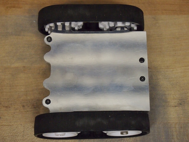
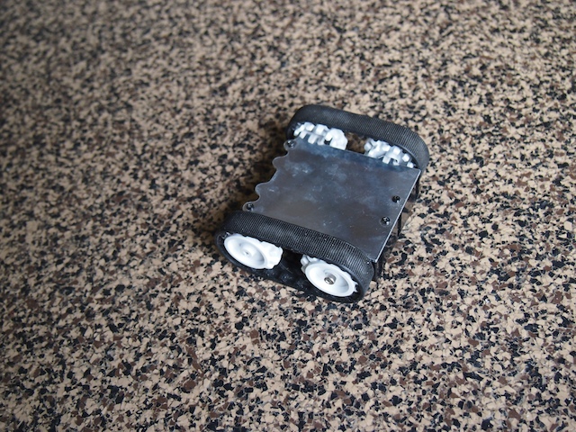
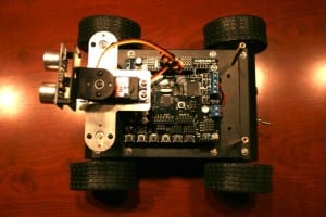
This is Tinybot. About 3″ long and just 1.5″ high, this is one of the smallest robots we’ve ever built. Starting with a Pololu Zumo drivetrain, we set out to see if we could get all the components of the robot INSIDE what was originally its 4 AA battery compartment. We used our CNC to make a cool aluminum top plate. Two tiny gear motors drive the rubber treads. We cut the pins off an xbee radio and soldered it directly to an Arduino Nano’s 3V pin and digital pins so that we didn’t need to waste space with an adapter board or wires. The robot also includes a tiny motor controller, a little 800 mAh 7.4V LIPO battery, and a rocker switch. This neat little robot works beautifully. It zips around with incredible agility, either via xbee-based remote control or through a pre-programmed autonomous pattern. It can drive forward, backward, turn, rotate, and even drive upside down. We built this robot quite a while ago and are just getting around to posting it now, but it was this little guy that gave us the confidence to know that we could build small intricate robots like Lunokhod and Mini Mars Rover.
Top view of our Tinybot with our custom CNC-machined aluminum top plate.
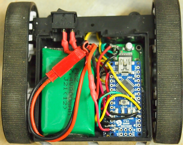
The Tinybot with the aluminum plate removed. The green thing on the left is the tiny LIPO battery. The blue thing is an Arduino Nano without headers. The motor controller circuit board and the hacked down Xbee module are laying flat below that, stacked in layers.
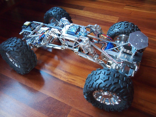
Today, we would like to introduce Terrabot, our Terrain Traveling Robot. Based on a modified “rock crawler” chassis, its primary purpose is to traverse rocks, branches, steep slopes, flower beds, boulders, mountain trails, and other extremely rough terrain.
Terrabot
Terrabot is equipped with 4-wheel steering (4WS). Two high torque servos shift machined aluminum linkages to rotate its front and back wheels independently. Note the navigation GPS on top of the back servo (on the left) and the sensor turret on the front (right). Terrabot’s four wheels are driven by two powerful brushless motors (bright blue) and robust gearboxes (centered in each axle).
Terrabot’s highly-articulated chassis is designed to twist up to 90 degrees as the robot is moving, allowing it to climb over huge boulders and other obstacles. In this picture, the chassis is articulated 45 degrees. Note that the back tires are still on the ground because the center linkages of the bot are twisted.
Terrabot’s topside electronics include a tiny Arduino Nano (lower left), an XBee Radio (right), and a 9-DOF Mongoose Inerntial Measurement Unit (IMU). The IMU measures the degree of tilt and the rate of acceleration in the X, Y, Z planes, which we plan to use for our stabilization algorithm.
Terrabot’s other electronics are stuffed into the little chamber inside the aluminum core (note the blue LED at the bottom of the picture). This includes the two Electronic Speed Controllers for the motors, the Pololu Maeastro motor/servo controller, the power rails, various voltage regulators, and other electronics. The navigation GPS (see the first picture), is mounted on top of the rear servo so that it has a clear view of the sky.
Terrabot Side View, showing the shocks, the frame, and LIPO battery beneath. Note the “roll posts” we installed on the top to protect the topside electronics if Terrabot falls off a rock during a climb and flips over. (We learned this one from experience!)
Terrabot Front View. There are three sonars mounted in the sensor turret, which rotates 270 degrees when the robot “looks around” to determine the best course through obstacle-ridden rough terrain.
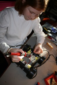
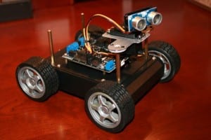
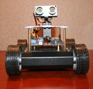
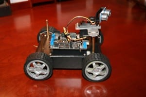
We have had a number of friends and family members ask how they can get started in robotics. They are interested in building a robot, especially a vehicle of some sort, but they don’t know where to begin. So, we have been working on the design for a small, inexpensive, easy to build, multifunctional, Arduino-based, programmable robot that will require basic robot building skills, but nothing too fancy. We call it “KitBot.” Our hope is to be able to help people get started. It will be able to function autonomously, but also by RC. It will include many off-the-shelf parts, a basic rover design, motors, servo, sonar sensor, sound, LED lights, and so on. These are our first pictures, which show the beginnings of the initial test project. It’s not done yet, but you can see the direction we’re moving. We have also sent all the parts to build a KitBot to a father and son team to be our initial Guinea Pigs (they wanted to try building it for a school project). As we work on refining the design and features, we’ll see how the father-and-son team does with the initial construction.
Soldering the power wires to the KitBot’s motorsAssembling our KitBot chassisKitBot: Top ViewKitBot: Corner ViewKitBot: Front ViewKitBot: Side View