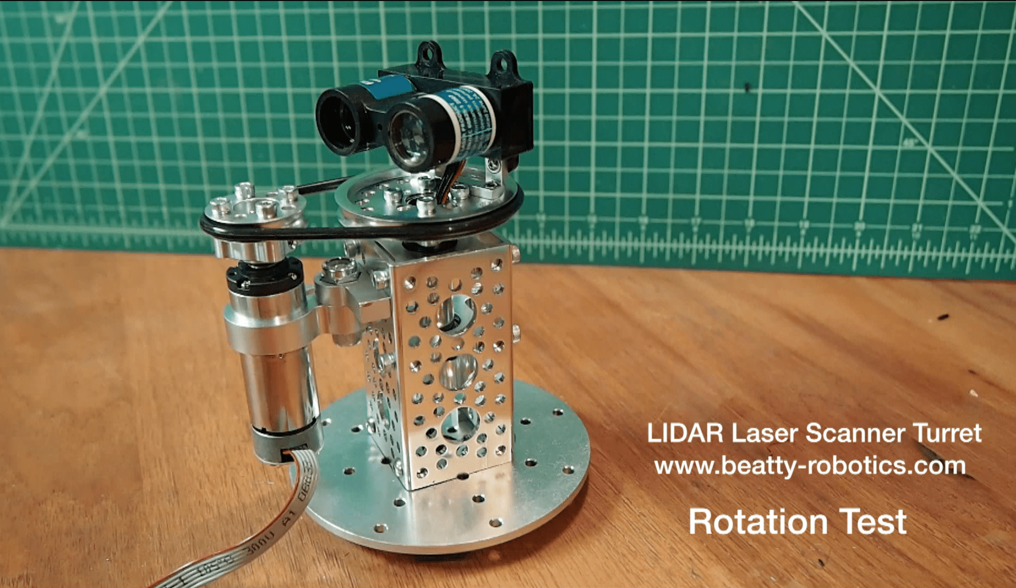
Recently, we encountered a new type of sensor that we’re hoping will really help our robots sense the world around them. We are avid users of Maxbotix ultrasonic sensors to detect objects, but they point in a single direction and only provide a somewhat fuzzy understanding of possible obstacles. So, instead of using sonar technology, we have now been experimenting with using LIDAR, which technically stands for “Light Detection and Ranging,” but we think of it as a mash-up of LASER and RADAR. In the past, LIDAR systems have been used by the military and other large organizations for mapping, target range determination, object detection, and other uses. They once cost many thousands of dollars. But recently, someone came out with a mini LIDAR sensor for $134. The true advantages of LIDAR is that it’s accurate, repeatable, and super fast. You can literally spin this little sucker around in a circle and it will spew out a series of numbers that represent the number of centimeters to every wall or object in the room. It will literally make a map of the room. As soon as I read about it, and saw the animated gif below, I knew I wanted to start working with this little scanner. It came as a great disappointment to me that the LIDAR unit itself was for sale, but there wasn’t a turret for it. That was just an artist’s animation. So, we decided to make our own. We built this little spinning LIDAR turret using an awesome combination of Actobotics parts. We also discovered something else we didn’t know about called a Slip Ring, which allows a collection of wires to spin around 360 degrees and never lose conductivity. So, here is a quick test of our newly assembled LIDAR Scanner Turret. It’s not perfect yet. We have some ideas for improvement. But it’s a good start.
Here is the original animation that was the inspiration for our LIDAR Scanner Turret. It shows how the LIDAR will spew out a series of distances to all the objects in the room. In this cases, it’s displaying those distances graphically on a computer screen. We plan to use the LIDAR Scanner Turret to give our robots situational awareness of the room they are in and all the objects around them. It will also be possible to add to tilting component to the turret, which will allow us to capture a 3D image of the entire room (although we’d probably need an Edison, Yun, or other Linux-based microcontroller to handle all that data rather than a simple Arduino). The future is bright. 🙂
Here is a picture of the Slip Ring, which allows us to spin the turret 360 degrees continuously, but still run wires to the sensor. The Slip Ring is housed in the 0.50″ hollow tube in the center of the turret.
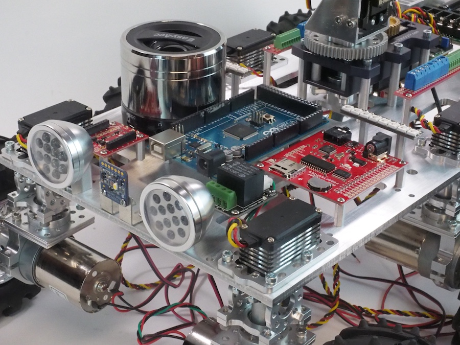
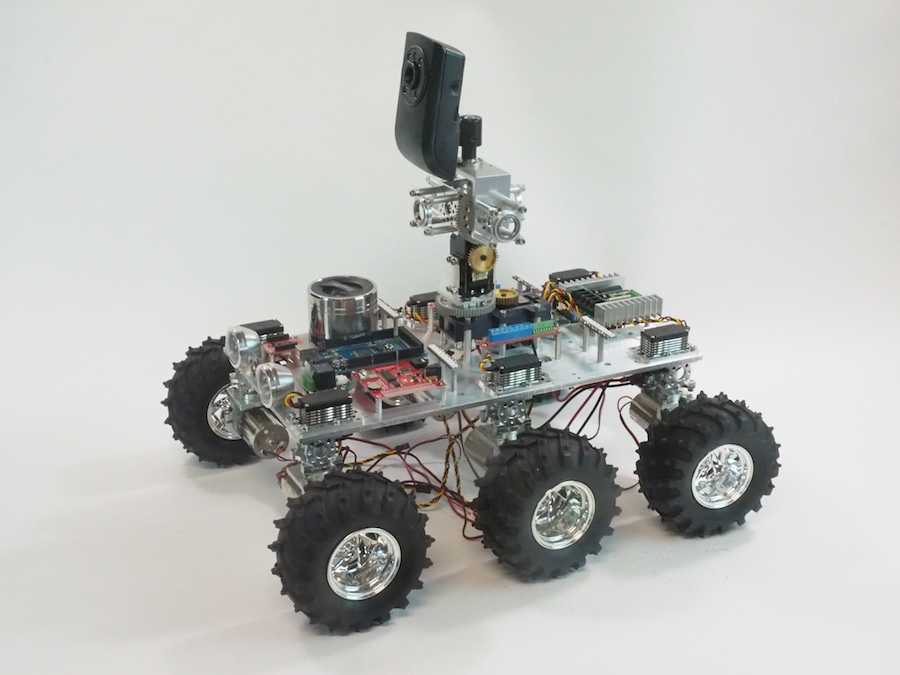
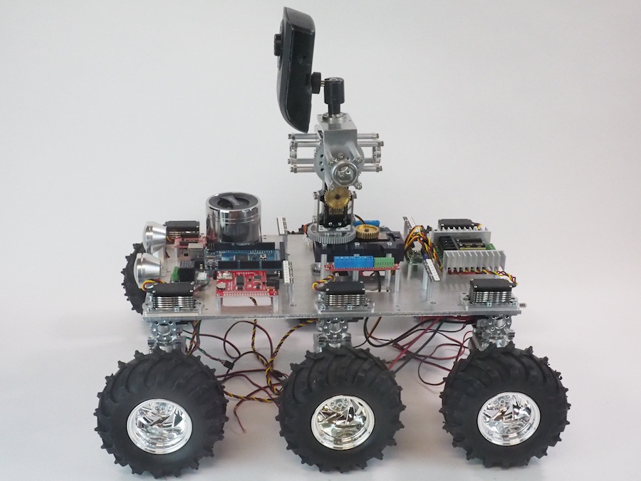
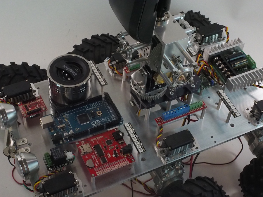
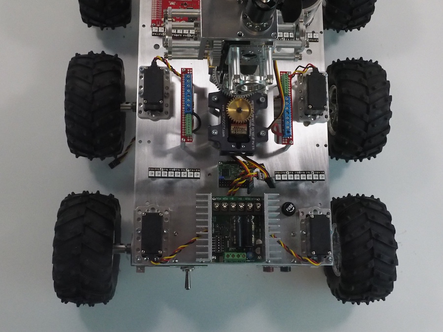
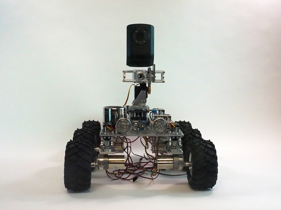
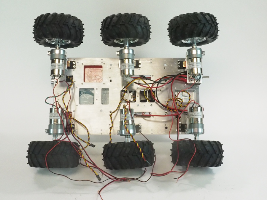
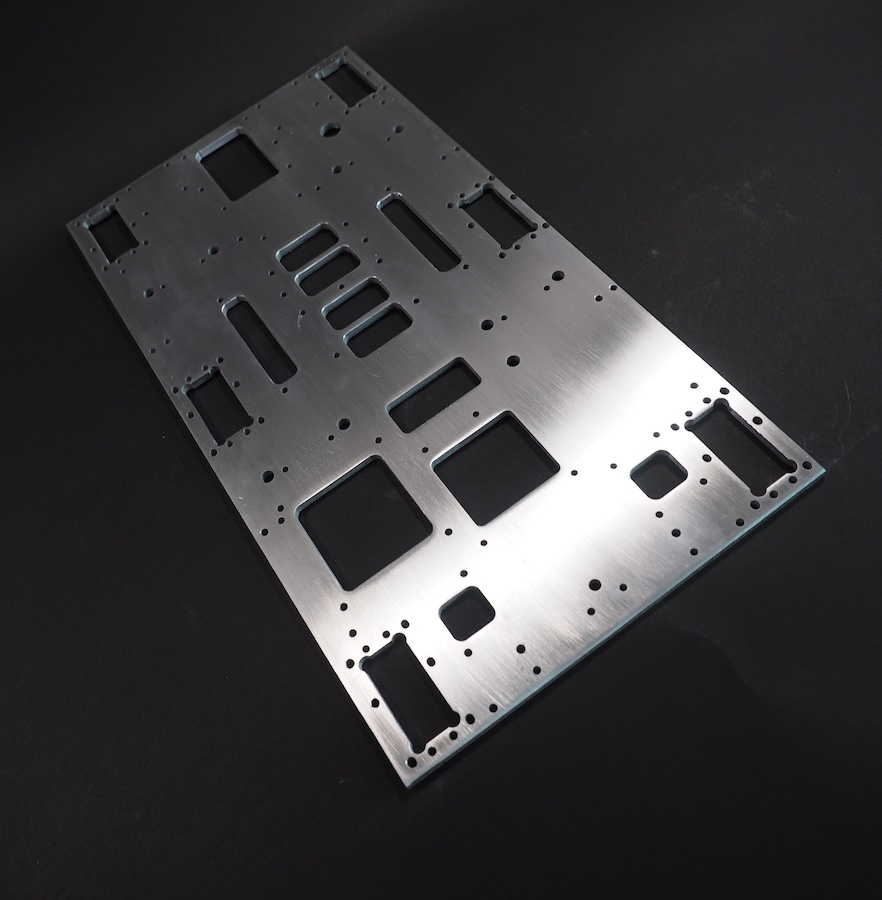
We’ve been working on the Rover Challenge robot for the New York Hall of Science. Its purpose is to give Science Center visitors a chance to drive a robot through an obstacle course, use ultrasonic and color sensors, record video, take snapshots, play music and sound effects, understand different types of steering, and learn about the various elements of a robot. Having completed the machining of the Main Plate, we are now assembling the various mechanical and electrical components onto it. The wiring isn’t done yet and some of the components are not yet installed. This is just a preliminary look at the direction we’re heading. The folks at NYSci asked us to make a compact six-wheeled robot that had a “homemade” or “science project” feel to it, so we’ve left all the electronic components exposed. This provides a good teaching platform with the various elements of the rover clearly visible, such as the Arduino, the motor controller, the servo controller, and so on. We will also be providing an optional clear acrylic top plate in case they wish to cover the components. This robot will have many features and options, including easily interchangeable wheels–either the knobby tires shown here or the gnarly metal wheels you might have seen in previous posts. Because each wheel is mounted on a servo, this rover will provide several different types of steering, including the rotational servo-steering we used on the Mars Rover and 90-degree strafing. It should be fun to see in action.
Today, we completed an important part of our new Rover Challenge robot for the New York Hall of Science. The central focus of this robot’s design is the Main Plate. This is an intricate aluminum part that we designed on the CAD system and machined on the CNC. It’s 8″ x 15″ x .190″. It’s meant to hold all the servos, electronics, camera turret, and other components of the robot, so it’s the chassis, mounting plate, and wire organizer all at once. It took a while to design it, but we’re very happy with it so far. Keep your fingers crossed we haven’t forgotten anything!
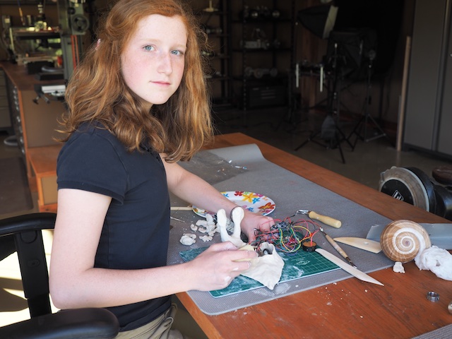
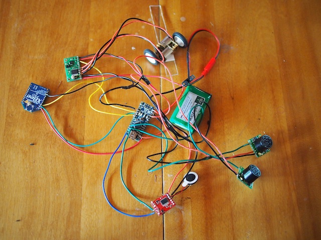
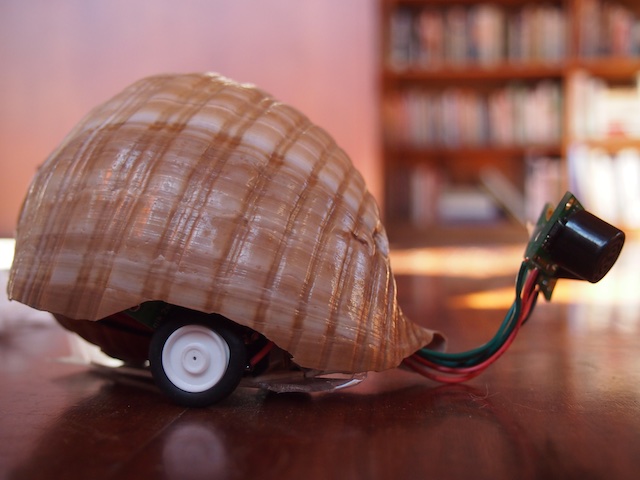
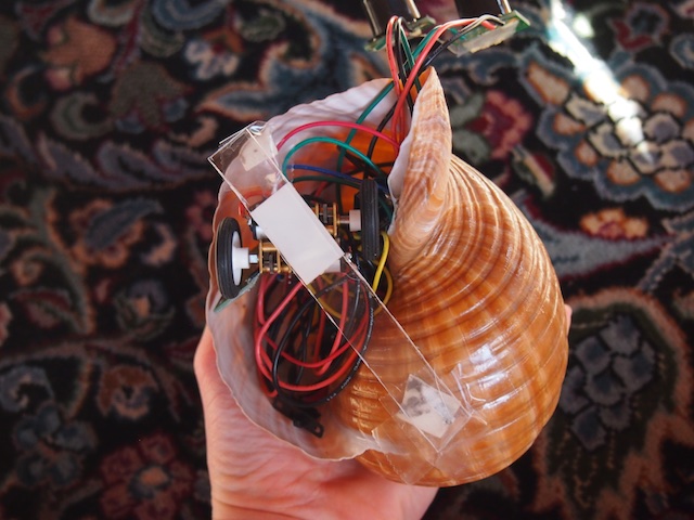
Snailbot is one of my favorite pet projects. 🙂 The idea is to build a robot inspired from a biological creature, in this case, a snail. The first challenge was to design and wire-up the electronics so that they would fit inside the limited space of the snail shell. The electronics include an Arduino Nano microcontroller, a motor controller, two tiny gear motors with wheels, a lithium-polymer battery, an xbee radio for data transmission and remote control, an SD card and sound module, a tiny speaker for sound effects, and two ultrasonic sensors that will serve as Snailbot’s eyes.
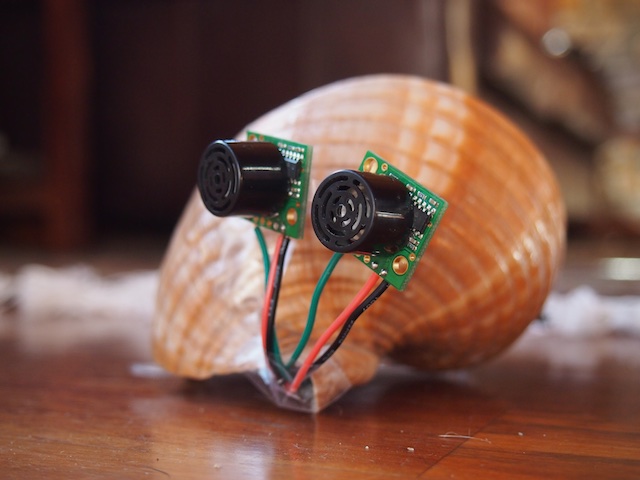
THE EYES OF THE ROBOT STICKING OUT OF THE SHELL PRIOR TO SCULPTING THE EYE STALKS
SNAILBOT SIDE VIEW PRIOR TO SCULPTING THE MOLLUSK PORTION OF THE ROBOT
SNAILBOT’S SHELL
THE ELECTRONICS IN THE SHELL
I’M MOLDING WET CLAY TO CREATE THE SOFT MOLLUSK PORTION OF SNAILBOT
SCULPTING THE EYE STALKS
Snailbot isn’t done yet, but I’ve made good progress.
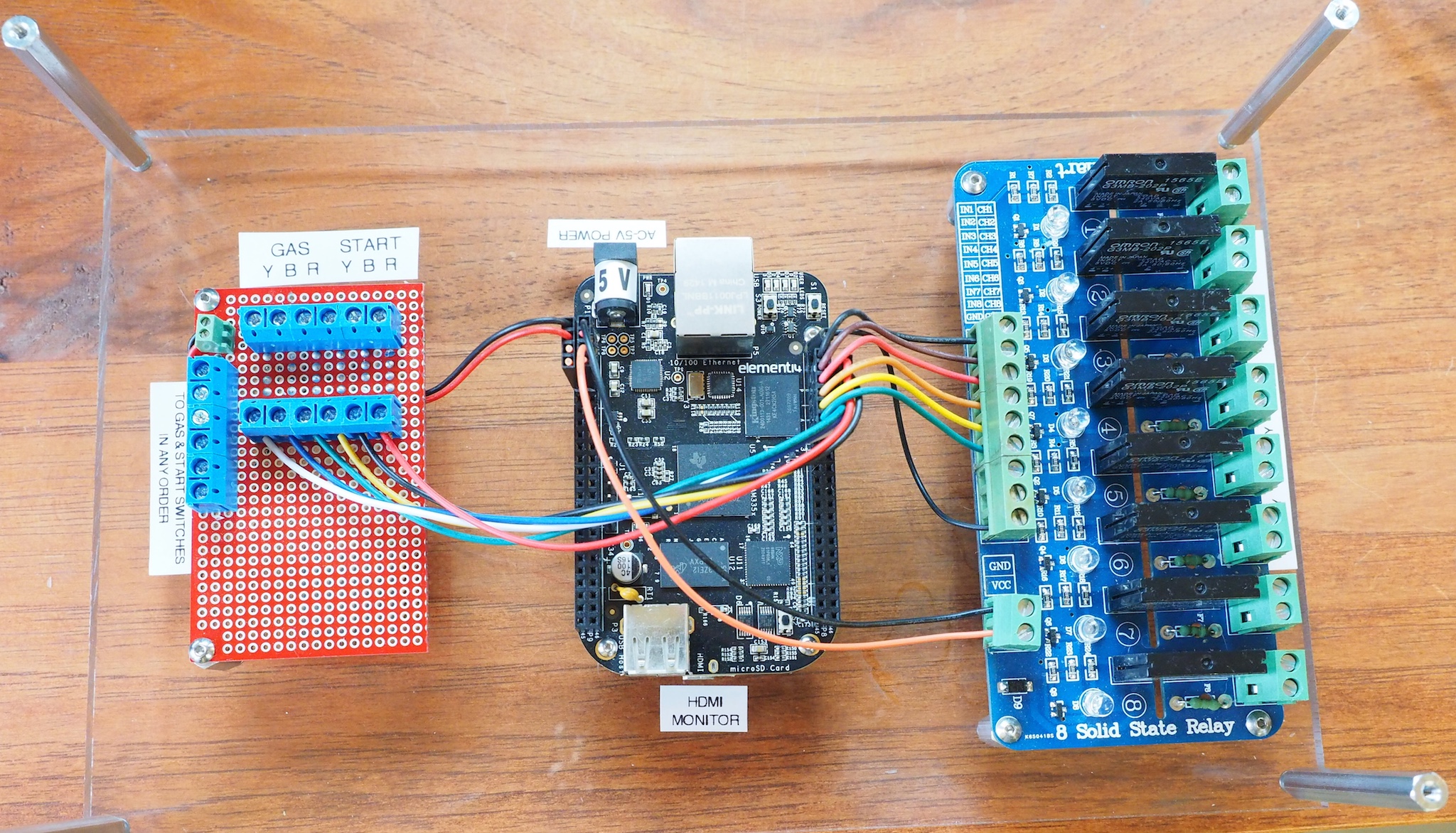
We are working on the electronics for a hands-on museum exhibit that tests reaction time and shows how you can improve their reaction time through practice. The main components of the control unit are a BeagleBone Black, an 8-Channel Relay Board (to control a set of race track staging lights), and a custom-made protoboard with resistors and screw terminals (that take input from the start buttons and gas pedals). The exhibit consists of three race cars. Each car has a start button and a gas pedal. When someone presses a start button, then a set of large staging lights count down Ready, 3, 2, 1, Go! The staging lights are similar to what you would see at a drag racing track. The system then measures the time it takes each driver to press his/her gas pedal. The results are displayed on a large monitor (connected to the BBB’s HDMI port) that everyone can see. If anyone presses his/her pedal too early, then the “Too Early!” light goes on and the screen indicates that it was a false start. The system also includes appropriately-timed drag racing sound effects output through the BBB’s HDMI port to an amplifier and set of speakers. Here is a picture of the control board we made. It will go inside a clear acrylic box to protect it. This is a Rev C BeagleBone Black running Debian Linux. The custom software is written in Python.