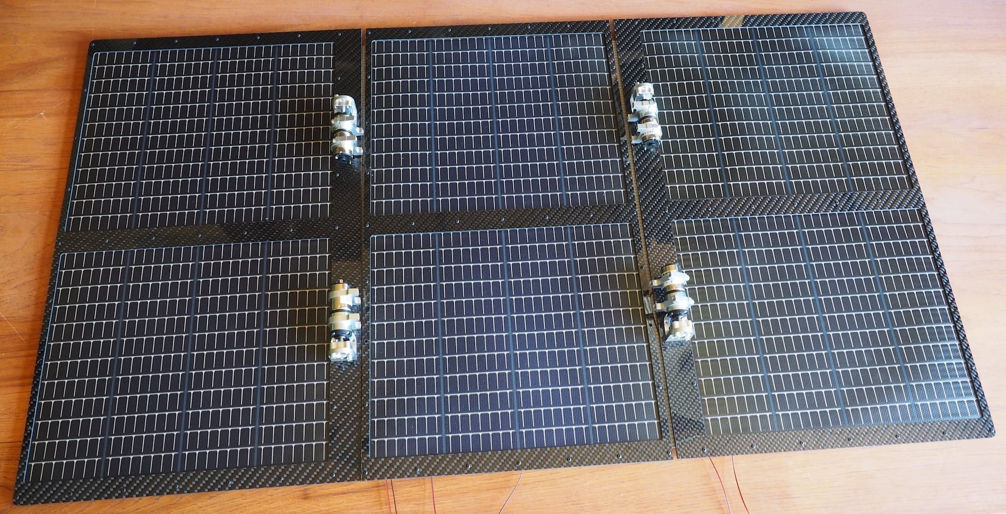
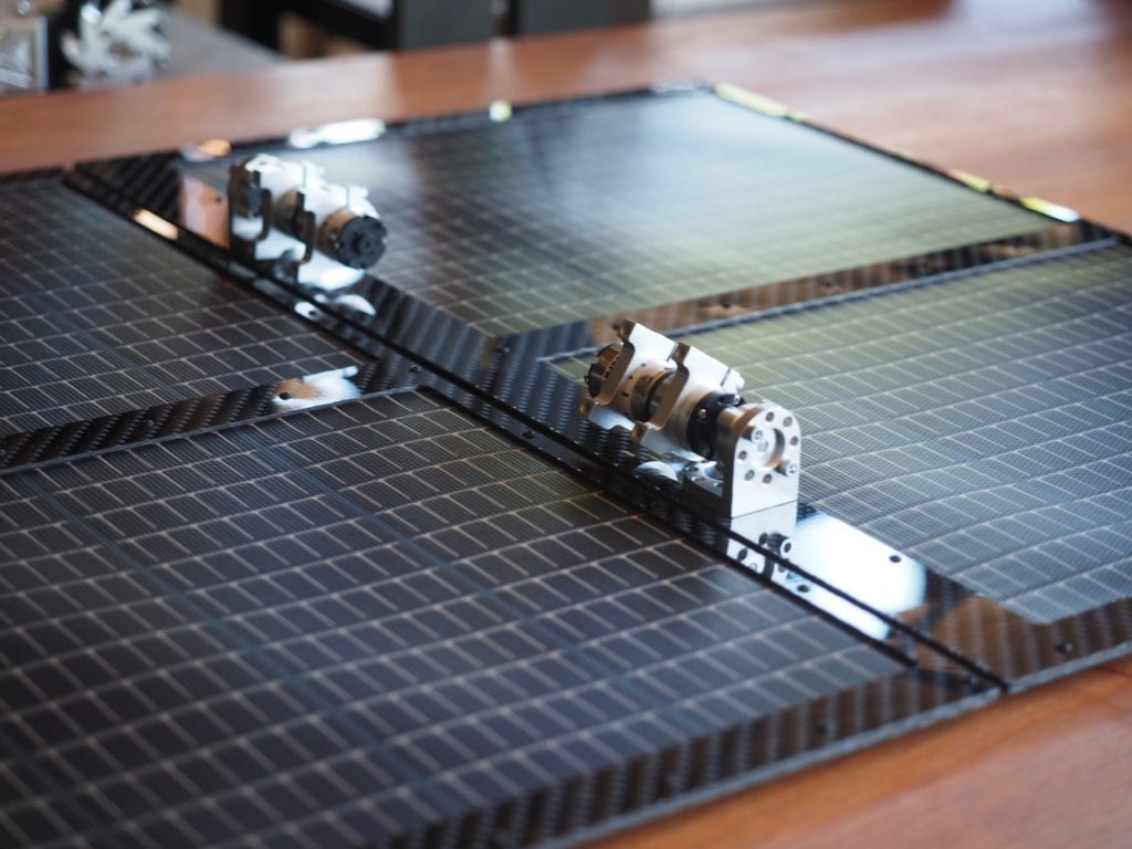
We have been working on the solar top for the Lunar Rover. The rover will use six 15.4V PowerFilm solar panels (PT15-300) to generate a total of 1.2 Amps @ 15.4V, which will be used to charge the 3-cell 12V lithium-ion battery. Each panel is 10.6″ x 12.8″. We selected the PowerFilm panels because they were thin, flexible, rugged, easy to work with, and came in a variety of shapes and sizes. We mounted the panels in between a sandwich of custom-designed, CNC-machined carbon fiber plates that we designed for the purpose. We used carbon fiber (provided by DragonPlate) because it was lightweight and rigid. The plates are held together with small, black, #2-56 screws. Because we wanted the area between the plates to be thin, we didn’t use our normal 24 AWG wire, which was too thick. Instead, we used copper conductive strip, which is flat. When mounted on the robot, two of the panels will be in the central, fixed position. There will also be a pair of panels on “solar wings” on each side. The wings will start out folded on top of the robot’s main body over the two fixed panels. When we want to deploy the solar wings, small motors will open them up like the pedals of a flower, exposing all six panels to the sun. This design allows us to keep the robot compact for transport, but have three times the surface area and therefore three times the current for charging the batteries.
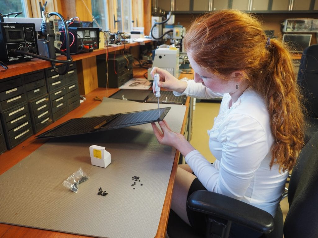
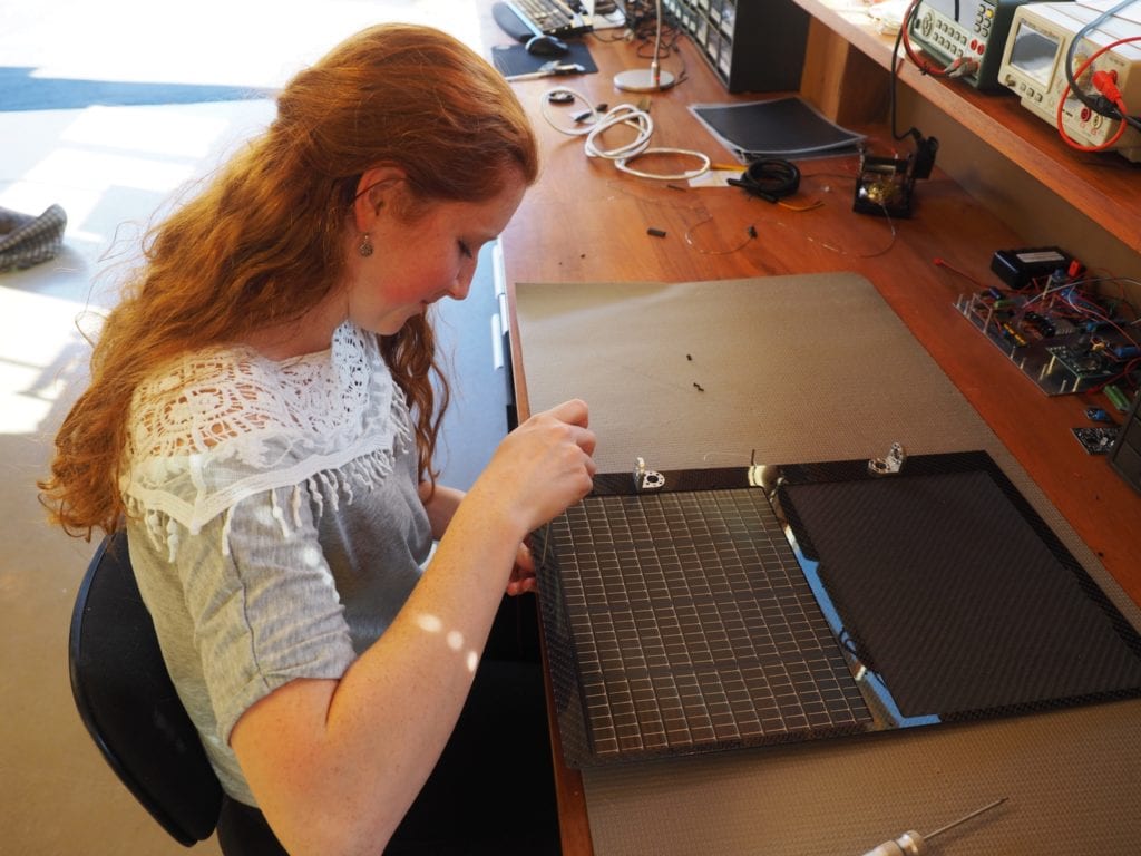
ASSEMBLING THE SOLAR PANELS BETWEEN THE CARBON FIBER PLATES
WE USED CARBON FIBER TO MINIMIZE WEIGHT, BUT MAXIMIZE RIGIDITY IN THE SOLAR WINGS
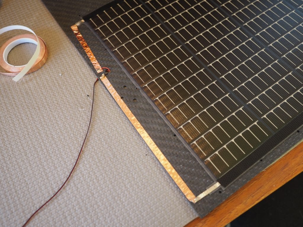
TO KEEP IT FLAT, WE USED CONDUCTIVE COPPER STRIP RATHER THAN WIRES. THE “FINGERS” (SHORT LINES) OF THE SOLAR PANEL POINT TOWARD THE NEGATIVE SIDE. THE “KNUCKLES” ARE ON THE POSITIVE SIDE.
WHEN THE SOLAR WINGS ARE MOUNTED ON THE ROBOT, THESE SMALL MOTORS WILL BE USED TO OPEN THE WINGS
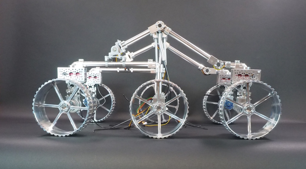
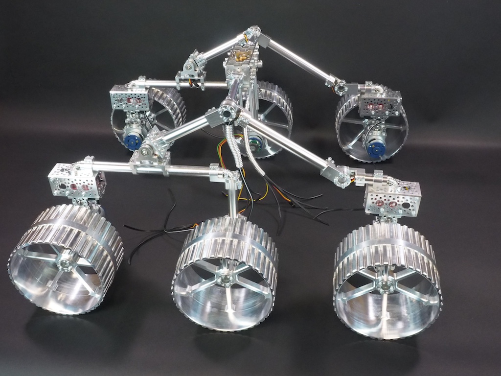
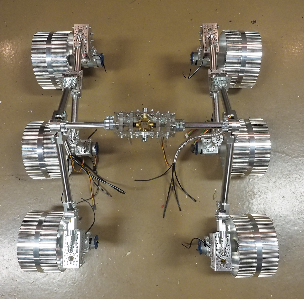
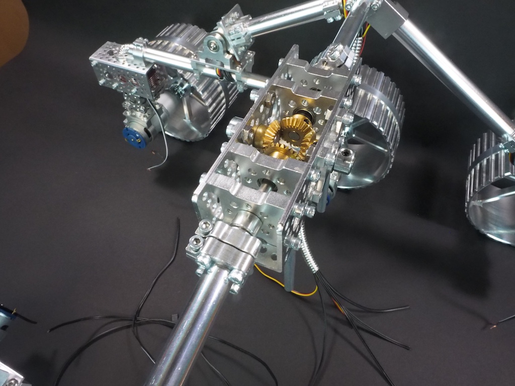
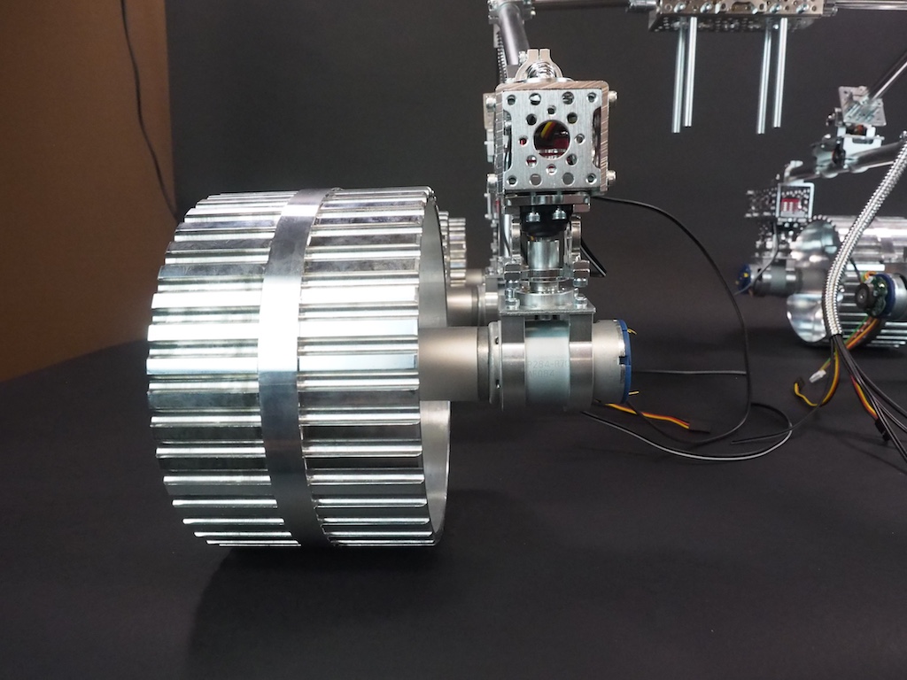
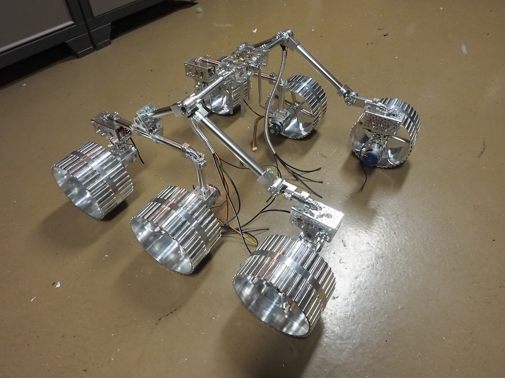
SpaceLS, a rocket company in the UK, has asked Beatty Robotics to team up with them to pursue a mission to put a rover on the moon. The first step in the process is for Beatty Robotics to design and construct a prototype for SpaceLS to use for testing, experimentation, and development. We’ve been working hard on the project, but we’ve been so busy we haven’t had time to take any pictures until now! Here are our first photos of the Lunar Rover’s rocker-bogie suspension system, counter rotating universal joint, steering servos, motors, and wheels. We designed the wheels to be large (6+” diameter) and wide for traveling through lunar ash. All the components of the robot will be machined out of aluminum, titanium, and carbon fiber. When it’s done, the robot will be solar powered and run on an Intel Edison. These are work-in-progress photos. The robot’s core/body, solar panels, video/sensor mast head, and other components are not shown.
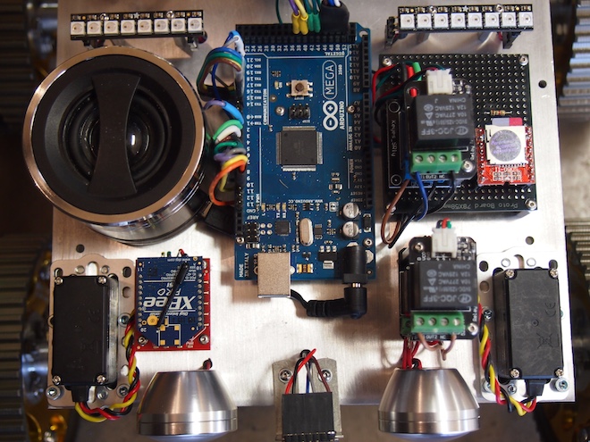
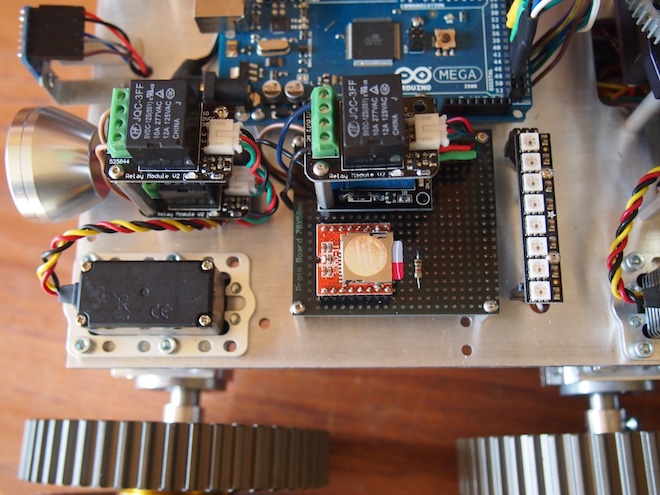
We often add sound effects and even music to our robots. We’ve used a number of approaches, but our latest method is the SOMO-II MP3 Module. Here are some pictures (from a rover robot we’re working on) and the technical details of how we integrated the SOMO module. First, here is a top view showing the speaker on the left, the Arduino in the middle, a stack of relays, and the SOMO (orange and silver colored square) on the right.
A closer view of the SOMO mounted on female headers soldered to a black protoboard. You can see the microSD card sticking out, which will give you an idea of how small the SOMO is. You can also see the 1K Ohm resister, which is required to get it to work.
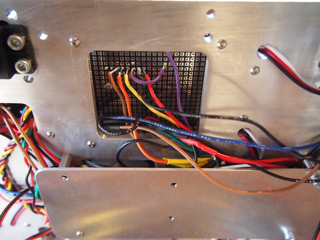
The underside of the prototype board. The SOMO is using the brown, orange, yellow, purple, black, and red wires. The other wires are unrelated.
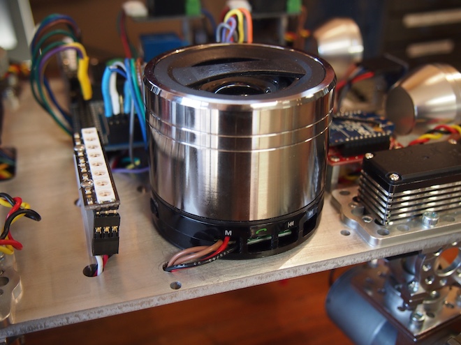
We took a powered USB speaker apart, hacked into it, and screwed it to the main plate. We pulled out the speaker’s battery and wired the speaker into the robot’s main 5V battery. We also rewired the speaker’s buttons so that we could control its functionality using an Arduino-controlled relay to change its mode so that it will receive an incoming external audio signal.
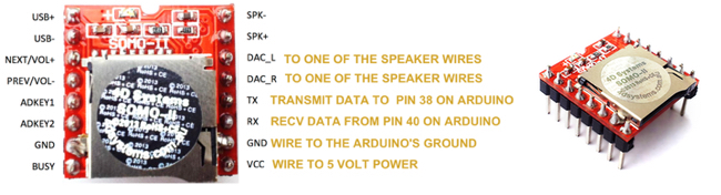
Here are the steps to get the SOMO setup: First, put your mp3 sound files onto a microSD card. The files should be in a folder called “01”. And they should be numbered 001xxxxx.mp3, 002xxxxx.mp3, and so on, where xxxxx is any name you want to give them (or no name at all, just the number prefix). The main thing is that the files need to begin with the numeric sequence as shown. Next, wire the SOMO to your Arduino and a powered speaker like this. We used Arduino pin 38 and 40 on our Arduino Mega, but you can use whichever suitable digital pins you wish to (or Serial1, Serial2, or Serial3 on a Mega).
Important Note: The SOMO operates at 3V. If your Arduino operates at 5V (which most do), then solder a 1K ohm resistor on the SOMO’S RX Line. For the speaker, purchase a small, powered USB speaker and cut open the stereo audio cable. You’ll see three wires: white, yellow, and orange. Solder the white wire to the project’s ground. Solder the other two wires to DAC_L and DAC_R. These provide “line out” for a stereo headphone jack, external powered speaker, or amplifier. If you are using a small, non-powered speaker, then use SPK- and SPK+ instead.
The Arduino source code was the trickiest part. We couldn’t find any libraries or examples of using the SOMO with Arduino, so we wrote our own. Thank you to Curtis Whitley for helping us to figure out how to calculate checksums. At the bottom of this post, we’ve provided a sample program that shows how to play an mp3 track from the microSD card. It provides an example of exactly how to operate the SOMO-II from an Arduino.
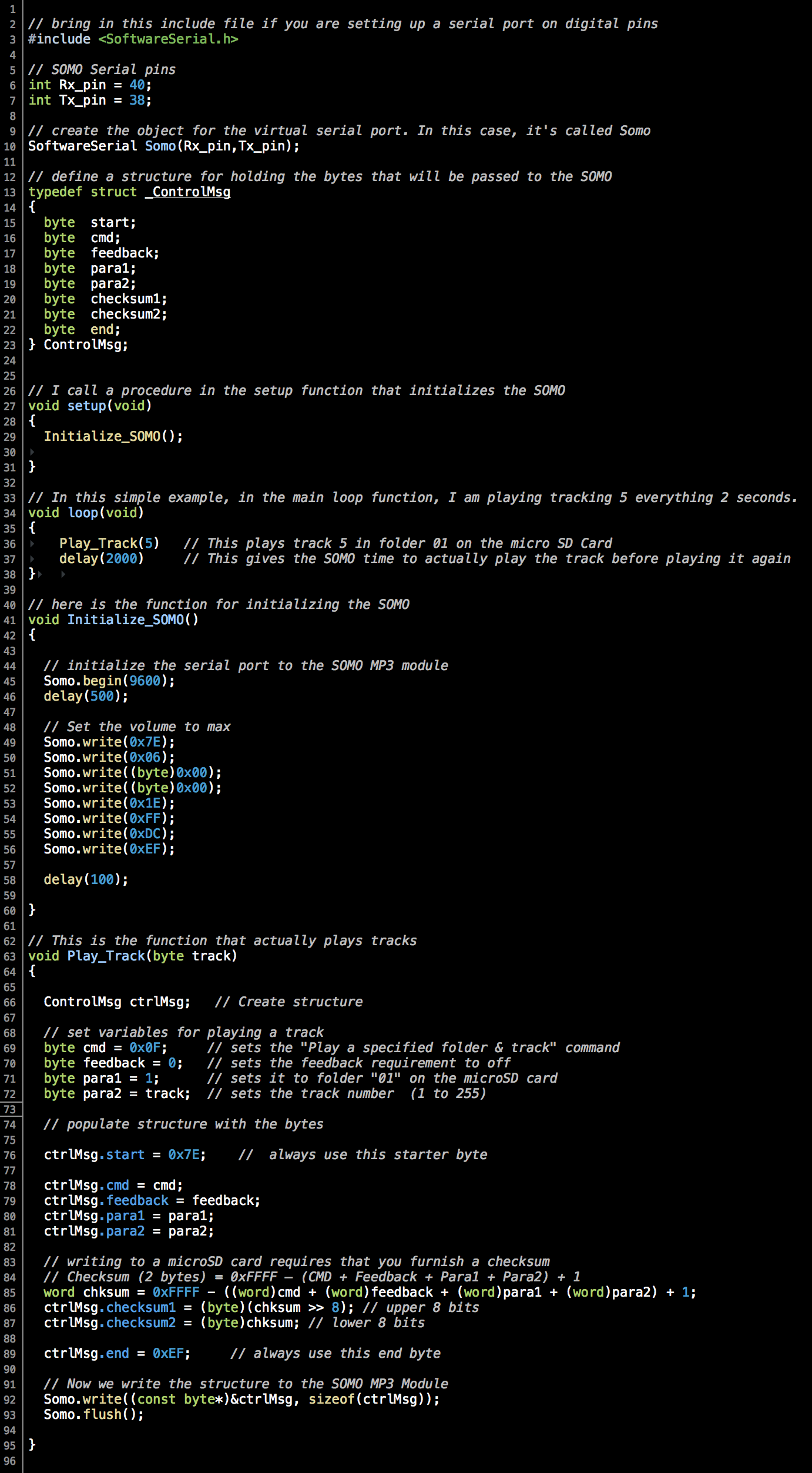
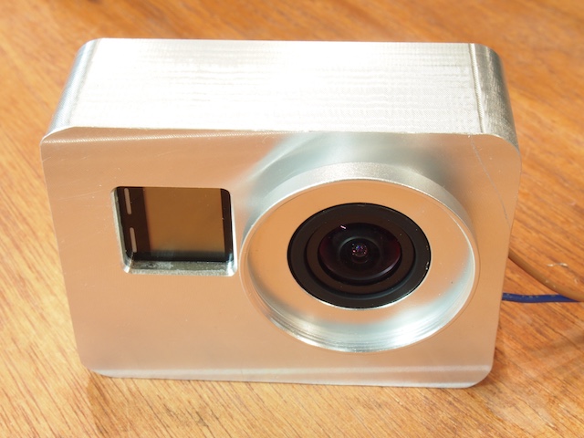
We are in the process of mounting a GoPro camera onto our latest robot. In our previous post we showed how we hacked into the GoPro and wired it up so that we could control it from the robot’s Arduino microcontroller. The next task was to design and machine a case for it. As usual, the CAD design work took longer than the actual machining. It was a fun and challenging little machining project. The end result isn’t perfect, but I think it came out pretty nice, and it will definitely serve the purpose. Our case needed to have these characteristics:
Protect the GoPro and make it look cool on the robot.
Provide slots for running the remote control wires.
Cover up all the GoPro’s buttons so that museum participants and technicians can’t play with the buttons (and mess up the settings in the camera). The camera will be entirely controlled by the robot.
Provide specialized tapped mounting holes for specific placement on the turret of our robot.
Provide a lens cover to protect the GoPro’s lens.
Provide space and protection for the HD transmission cable and modified USB cable plugged into the side ports.
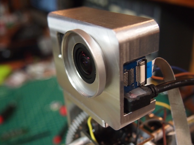
FRONT VIEW OF CAMERA IN CASE
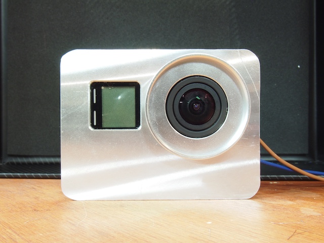
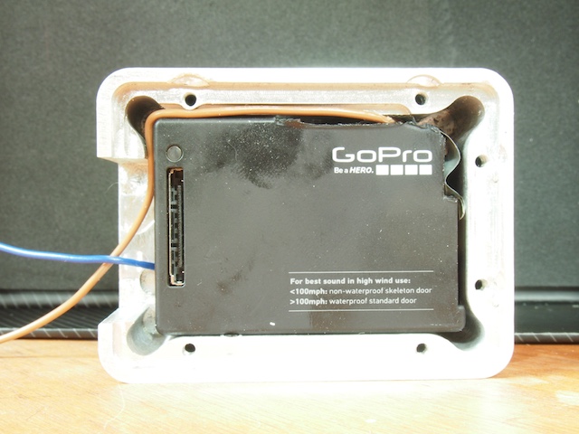
REAR SIDE WITH REMOVABLE PLATE
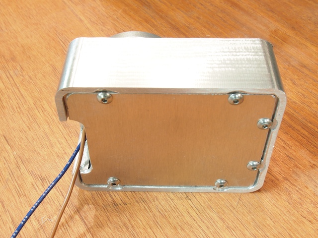
CORNER VIEW SHOWING HD CABLE AND USB CABLE PLUGGED INTO PORTS
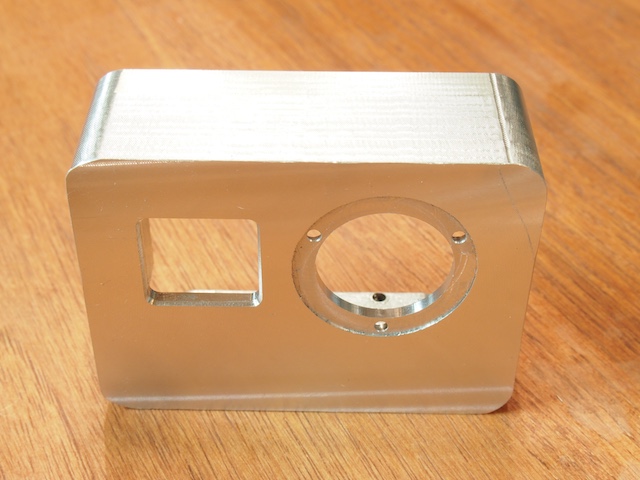
EMPTY CASE BODY MACHINED ON CNC
REAR OF THE CASE BODY SHOWING WIRE SLOTS AND OTHER DETAILS
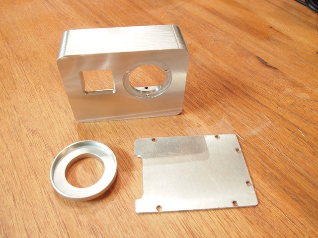
THREE COMPONENTS OF THE CASE (2 custom machined parts + a lens circle hacked from something else)
Sometimes there are situations where it’s useful to control a GoPro by wired remote control and/or to integrate a GoPro into a DIY electronic project. This seems like it should be straight forward, but it’s not. I searched for a third party cable or module to plug into one of the GoPro’s ports, but as far as I can tell, there is nothing readily suitable on the market. So, in this post I describe how we hacked into a GoPro Hero 4 Black in order to integrate it into a robot we’re building.
First, we tried communicating through the Hero Port (the large port on the back of the camera). This seemed very promising. You can do some neat things with this port. But unfortunately, controlling the GoPro’s shutter button isn’t readily feasible because GoPro didn’t set it up as a simple digital pin. Instead, they created a proprietary communication protocol that they purposely do not publish. They don’t want people to hack into their cameras. Next we tried using the USB port, to no avail. Then we tried hacking into the wireless remote control, which we were able to do pretty easily, and it sort of worked, but it did not provide the speed and reliability we needed. So, in the end we went old school. We tore the GoPro apart, hacked into the case, and soldered wires to the button rings. It isn’t pretty or elegant, but it works. Here are the details of what we did:
1. First, we needed to integrate the GoPro’s power into our robot. We didn’t want to have a separate battery. So we removed the battery completely, plugged a mini USB cable into the USB port on the side of the GoPro, and hacked the other end. The Hero 4 will run entirely off a USB cable with no battery in it. If you cut open a USB cable, you’ll see four or five wires. Normally the red is positive voltage and the black is ground. If you don’t see a red and black, then Google USB wire color codes for further clues. We connected the red wire to the robot’s 5v regulated power rail. So now, when the robot has power, the GoPro has power. When the robot goes off, the GoPro goes off. Another option is to use a Switronix Battery Eliminator, if you would prefer to use the GoPro’s Hero Port.
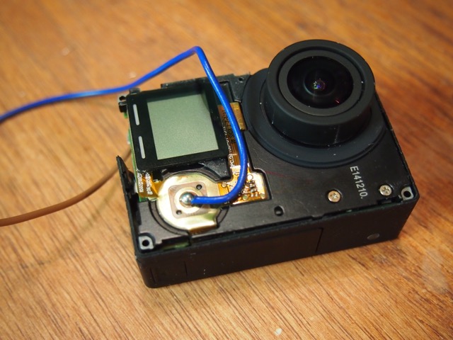
2. Second, we needed to turn on and control the GoPro from the robot, specifically from an Arduino micorcontroller. Note: A GoPro does not turn on just because it has electrical power. In order to operate the camera, you need to press the Power/Mode button (on the front) and the Shutter/Select Button (on the top). The following instructions voids your warranty, causes irreversible damage to certain parts, and has an extremely high potential of turning your $500 GoPro into a mess of useless bits of metal, plastic, and electronics. Welcome to DIY hacking!
A. Use your fingernail or a prying tool to remove the front facade. It’s stuck down with adhesive and two little plastic clips on each of the four sides. This takes time and patience. The front plate is thin aluminum. Unless you’re very careful, you’ll end up bending it. You will probably be wanting to put the plate back in place when you’re all done, so be careful.
B. Next, use a small electronics screw driver to unscrew four screws to loosen the electronics.
C. Separate the case from the electronics at the port end first, carefully prying and wiggling until you are able to pull out the electronics. Again, this will take time and patience. Be careful.
D. As the electronics come out, you’ll see there are two main sub-assemblies connected by a thin, delicate orange flat ribbon. Try to keep the sub-assemblies together. If you fail at this, you’ll pull out the ribbon connector. It’s a major pain and risk to put that tiny thing back into place. However, it is doable. It took twenty minutes of fussing, but we managed to do it.
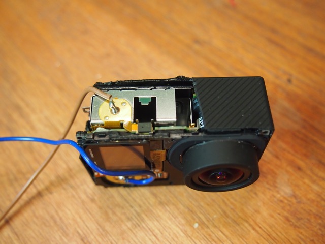
E. Use big snippers and other tools to cut away the top part of the case to expose the Shutter/Select button on the top. I wish there was a better way, but we could not find one.
F. Use your fingernail to scrape off the little white touch area beneath the Shutter/Selection Button.. Solder a wire to the tiny central circle (be very careful not to connect the outer circle to the inner circle). Run the wire to a relay controlled by your Arduino. Use the relay to close the circuit to ground using a digitalWrite command.
G. Do the same thing on the Power/Mode Button, which is on the front of the camera.
H. Replace the case and physically integrate the camera into your project. In our situation, we have machined a special aluminum case that we designed specifically to meet the needs of our particular project. When it’s all done, the mangled plastic GoPro case will not be visible in any way.
After doing the steps above, we now have two wires coming out of our GoPro. We’ll attach each wire to a little relay module, which in turn we will control with two digital pins on our Arduino. We’ll then use simple digitalWrite commands to operate the two relays, giving us complete control of the GoPro.