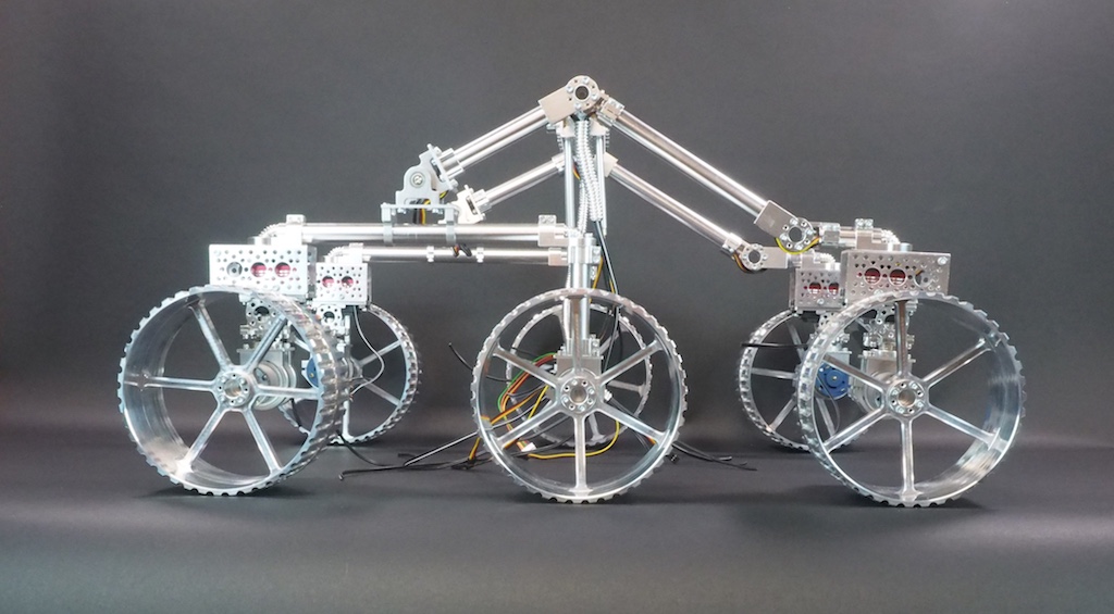
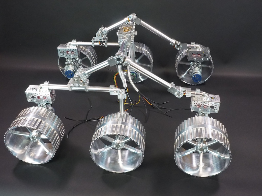
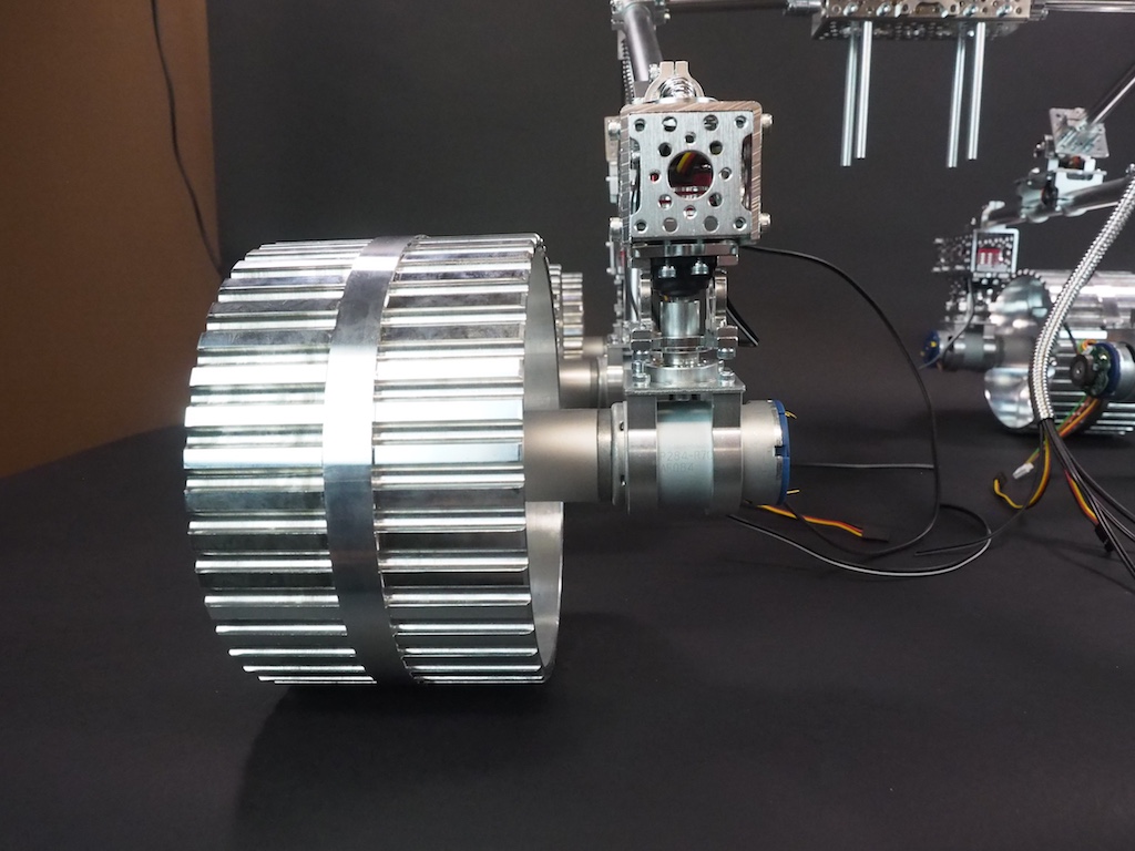
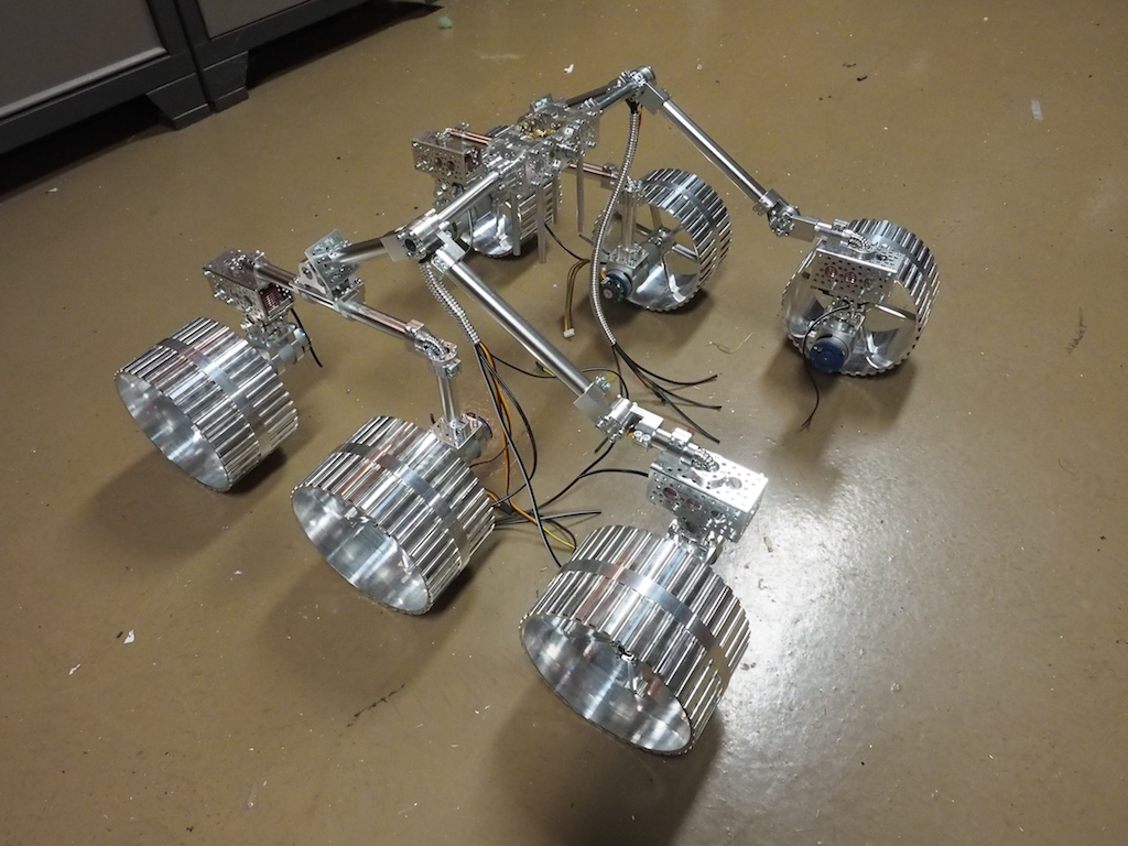
SpaceLS, a rocket company in the UK, has asked Beatty Robotics to team up with them to pursue a mission to put a rover on the moon. The first step in the process is for Beatty Robotics to design and construct a prototype for SpaceLS to use for testing, experimentation, and development. We’ve been working hard on the project, but we’ve been so busy we haven’t had time to take any pictures until now! Here are our first photos of the Lunar Rover’s rocker-bogie suspension system, counter rotating universal joint, steering servos, motors, and wheels. We designed the wheels to be large (6+” diameter) and wide for traveling through lunar ash. All the components of the robot will be machined out of aluminum, titanium, and carbon fiber. When it’s done, the robot will be solar powered and run on an Intel Edison. These are work-in-progress photos. The robot’s core/body, solar panels, video/sensor mast head, and other components are not shown.


beautiful!
Thank you! 🙂
As always, this is great! As a long-time follower of this blog, I love the inspiration of seeing two accomplished sisters involved in STEM.
Very nice!
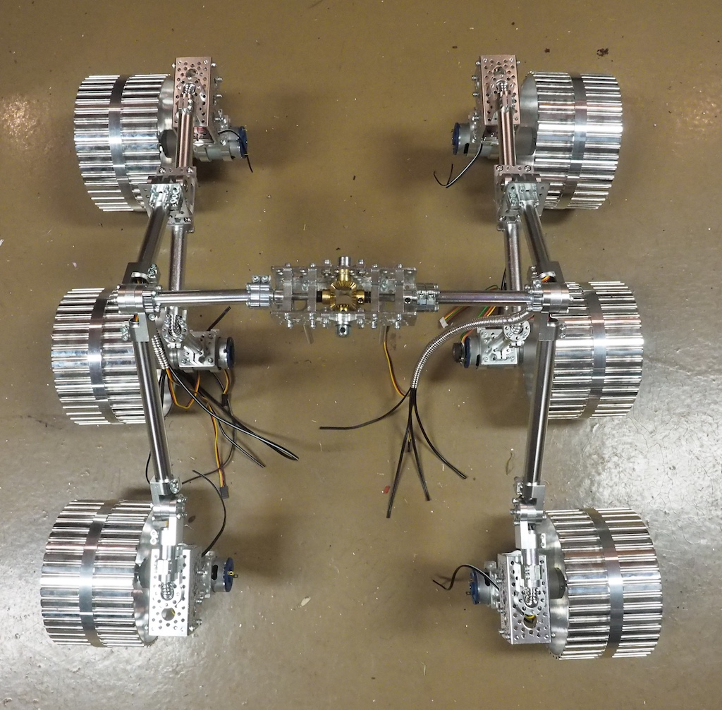
I really like the PRR design between the rear four and front two wheel sets, lots of flexibility for traversing rough terrain.
Good luck!
Thanks for the comment. We’ll take more pictures as the girls are working. I didn’t realize that was one of the main interest areas.
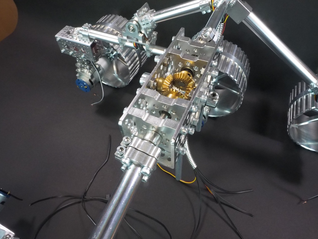
Fascinating design. At first I was baffled by what looks like a differential at the apex of the vehicle, but I take it that’s to allow the two sides to move independently of one another?
That is indeed a differential. I call it a counter-rotating universal joint (CRUJ). When the front wheel on one side goes up, the differential pushes down on the back wheels on the opposite side, giving the robot the traction it needs to climb the obstacle. It also averages (halves) the pitch of the core (the electronics box)(Which is not yet shown). It’s one of the sub-assemblies of the overall rocker-bogie suspension system.
Looking GREAT! 🙂
Great work sir.
Great and precise works.. I can not stop looking..:)
Excellent!
I just saw the video for those wheels on the NYC CNC youtube channel. They look even better on the rover. Can’t wait to see it with the body.
Wow!! Thats awesome lunar rover.
If it will be delivered on moon first solar flare will fry that electric motor wires. You should considering using diferent motors.
Also motors required faraday cage shielding and titanium plates to cover from micro meteorites impact. You should also think how you shield these wheels from micro meteorites. You might need foam and aluminum foil shielding like turtle have before putting on solar cells.
Good luck width your project and i hope moon pictures wont be bluried like nasa doing 🙂
Thanks for the tips, Ernest. This is a functional, scale prototype. The one that we launch to the moon will have various differences, including Maxon motors, but before we installed those, we wanted to experiment with various speeds, torques, and gear ratios using these preliminary motors. I don’t understand your phrase “like turtle have before putting on solar cells.” What do you mean?
it’s beautiful, i love the aluminum color haha. I have only one question that i cant figure out myself. Above four of the six wheels there is a small box. What are they for? thanks and good job so far.
Above each corner wheel there is a servo motor that is used to rotate the wheel. This is how the rover turns. It will rotate the corner wheels by 45-degress, then rotate in place.