Up to this time, we’ve been using hand tools to build our robots. But over the last few months, we’ve been working on building a Computer Numerical Control Machine (CNC) that will allow us to precisely cut, drill, and machine aluminum, brass, plastic, wood, and other materials.
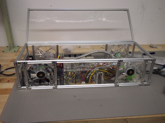
Part of this project is to design and build a custom electronics enclosure that will be a combination computer / CNC / motor control system. This will be the “brain” of the CNC. After trying a few different approaches, we decided to build the box from scratch out of 1/8″ acrylic sheet and Microrax, with are tiny, 10mm 80/20 aluminum beams. The enclosure is about 22″ long, 12″ wide, and 8″ deep. The beauty of Microrax is that we could easily cut the beams to the size we wanted and then use small machine screws and brackets to bolt them together. This allowed us to not only construct the overall enclosure, but to bracket the four cooling fans into place, frame the I/O ports, and add an acrylic lid with hinges. MicroRax is very flexible and cool stuff that I look forward to using for future projects, not only for enclosures, but robots as well.
CNC Electronics Enclosure
On the left side of the enclosure we mounted a mini-ITX motherboard, a small SSD hard drive (not visible in this picture because it’s under the motherboard), the RAM (blue), an internal USB hub, ports for communication with the motor controller, and various other computer components. In the center of the enclosure we installed the main power supply (clear) and the fan control system (black). The right side of the enclosure will contain the motor control boards and other CNC-specific components (which we haven’t installed yet).
There are four main enclosure fans (two on the top and two on the bottom) and four smaller internal fans.
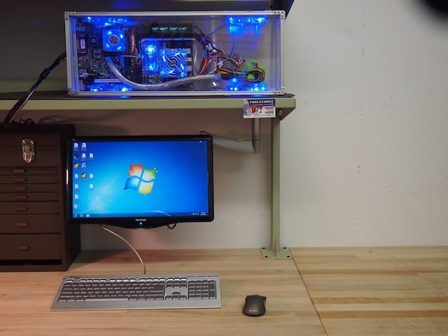
Here is the CNC Electronics Enclosure in the workshop, along with the screen, keyboard, and mouse. We will most likely be mounting the enclosure on the wall so that the lower two fans are more effective.[/caption]
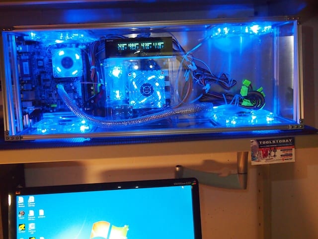
In this close-up, you can see that the fan control system displays the rpm speed of each fan and allows you to adjust it. It also displays the temperature of the corresponding sensor. We’ve attached the sensors to the microprocessor heat sink, the RAM, the motor controllers, and other critical components.[/caption]
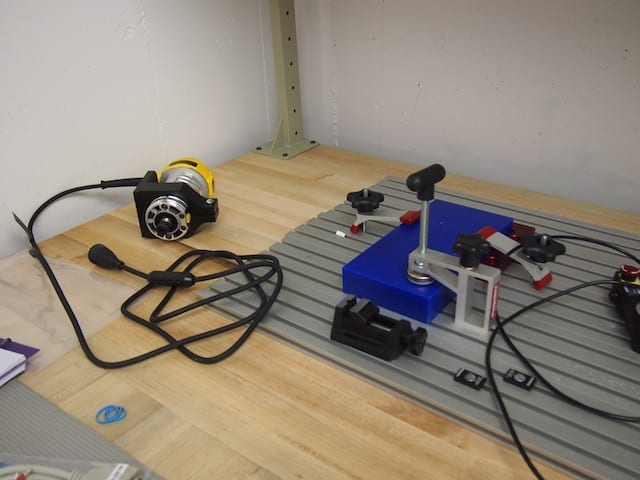
Here are various parts for the CNC that we’ve been working on, including the CNC’s aluminum T-Slot table, various fixtures, the largest of the three interchangeable spindles the CNC will use (for 1/4-inch end mills), and a block of blue machinable wax.
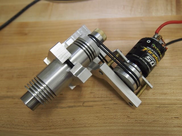
Here is a close up of the smallest spindle the CNC will use. This is a high-precision 1/8-inch spindle for delicate work. It will be driven at a spindle speed of 25,000 rpm by the brushed motor via the two black belts, which in turn will be controlled by the motor controller, which in turn will be controlled by the CNC software running on the computer. At least theoretically! Keep your fingers crossed! :)[/caption]
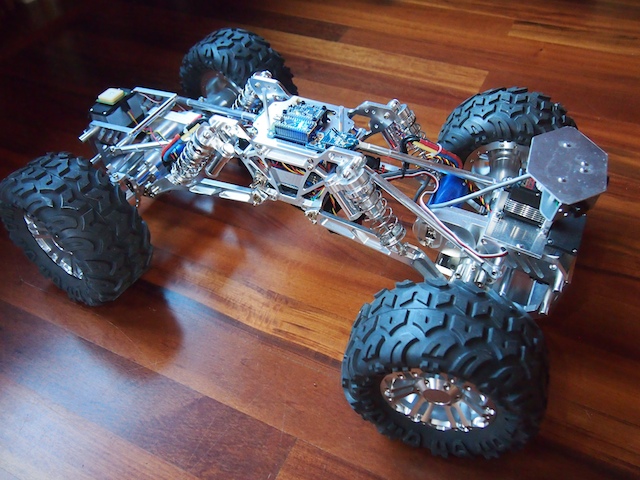
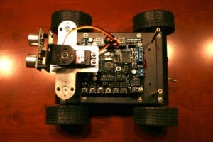
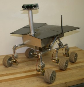
Today, we would like to introduce Terrabot, our Terrain Traveling Robot. Based on a modified “rock crawler” chassis, its primary purpose is to traverse rocks, branches, steep slopes, flower beds, boulders, mountain trails, and other extremely rough terrain.
Terrabot
Terrabot is equipped with 4-wheel steering (4WS). Two high torque servos shift machined aluminum linkages to rotate its front and back wheels independently. Note the navigation GPS on top of the back servo (on the left) and the sensor turret on the front (right). Terrabot’s four wheels are driven by two powerful brushless motors (bright blue) and robust gearboxes (centered in each axle).
Terrabot’s highly-articulated chassis is designed to twist up to 90 degrees as the robot is moving, allowing it to climb over huge boulders and other obstacles. In this picture, the chassis is articulated 45 degrees. Note that the back tires are still on the ground because the center linkages of the bot are twisted.
Terrabot’s topside electronics include a tiny Arduino Nano (lower left), an XBee Radio (right), and a 9-DOF Mongoose Inerntial Measurement Unit (IMU). The IMU measures the degree of tilt and the rate of acceleration in the X, Y, Z planes, which we plan to use for our stabilization algorithm.
Terrabot’s other electronics are stuffed into the little chamber inside the aluminum core (note the blue LED at the bottom of the picture). This includes the two Electronic Speed Controllers for the motors, the Pololu Maeastro motor/servo controller, the power rails, various voltage regulators, and other electronics. The navigation GPS (see the first picture), is mounted on top of the rear servo so that it has a clear view of the sky.
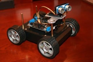
Terrabot Side View, showing the shocks, the frame, and LIPO battery beneath. Note the “roll posts” we installed on the top to protect the topside electronics if Terrabot falls off a rock during a climb and flips over. (We learned this one from experience!)
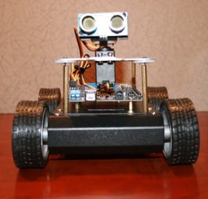
Terrabot Front View. There are three sonars mounted in the sensor turret, which rotates 270 degrees when the robot “looks around” to determine the best course through obstacle-ridden rough terrain.
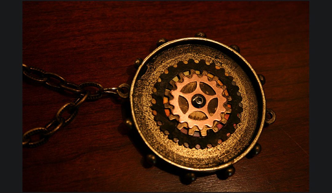
Earlier today we added a post announcing our Steampunk Necklace is now for sale. As usual, this posting was automatically emailed to all subscribers just like any other new post, but it was a bit misleading because the “Buy Now” button appeared in the email. Unfortunately, the Buy Now button doesn’t work from within the email page.
In order to make a purchase, you need to actually go to the website itself:
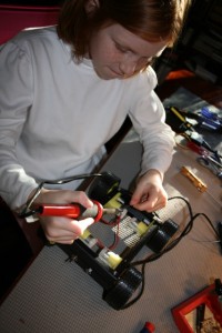
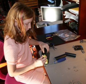
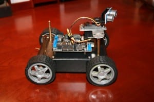
We have had a number of friends and family members ask how they can get started in robotics. They are interested in building a robot, especially a vehicle of some sort, but they don’t know where to begin. So, we have been working on the design for a small, inexpensive, easy to build, multifunctional, Arduino-based, programmable robot that will require basic robot building skills, but nothing too fancy. We call it “KitBot.” Our hope is to be able to help people get started. It will be able to function autonomously, but also by RC. It will include many off-the-shelf parts, a basic rover design, motors, servo, sonar sensor, sound, LED lights, and so on. These are our first pictures, which show the beginnings of the initial test project. It’s not done yet, but you can see the direction we’re moving. We have also sent all the parts to build a KitBot to a father and son team to be our initial Guinea Pigs (they wanted to try building it for a school project). As we work on refining the design and features, we’ll see how the father-and-son team does with the initial construction.
Soldering the power wires to the KitBot’s motorsAssembling our KitBot chassisKitBot: Top ViewKitBot: Corner ViewKitBot: Front ViewKitBot: Side View
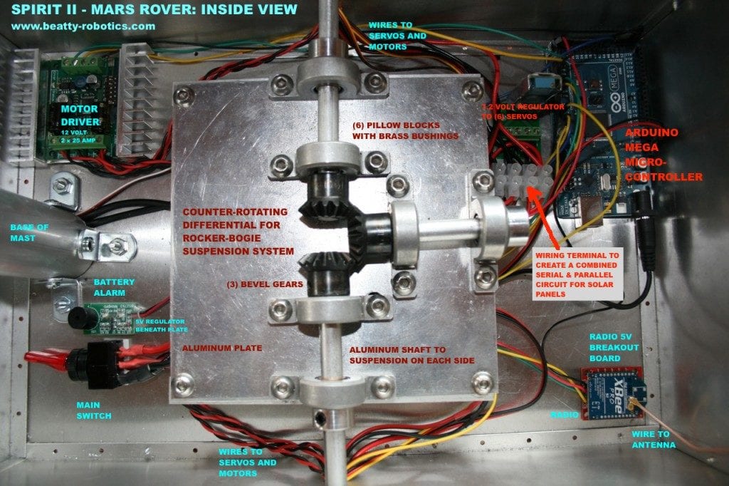
Several readers have requested an inside view of our Spirit II – Mars Rover so that they can see what the electronics look like. We have provided an annotated picture below, along with a couple of external shots.