by Camille | Workshop Blog
Here are some pictures as we continue work on our new Mars Rover.

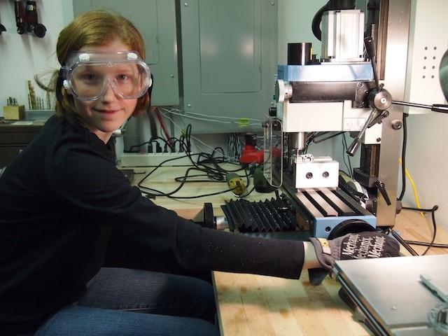
I’m using the vertical mill to modify an aluminum part for the Mars Rover. Cutting, drilling, and machining metal is my favorite area of work now. I’m turning into a good machinist.
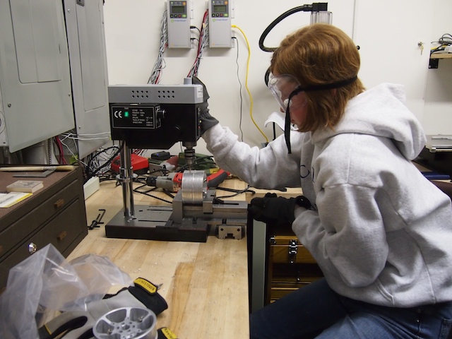
I’m using our mini drill press to drill holes onto the metal wheels in preparation for tapping the threads.
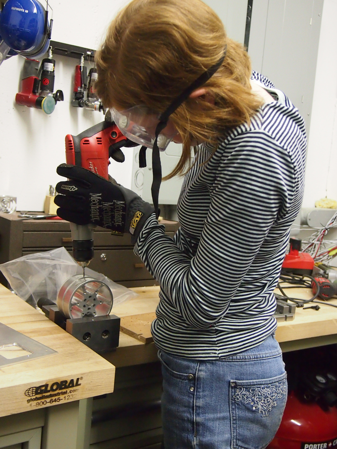
A new skill: I use our largest Milwaukee drill to tap 6-32 threads into the holes she drilled into metal wheels. The threaded holes will be used to secure the tread to the wheel (we don’t like glue). Tapping threads is very tricky (it’s very easy to snap the tapping bit), but she does a splendid job.
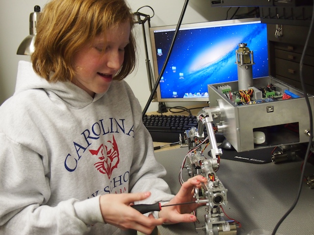
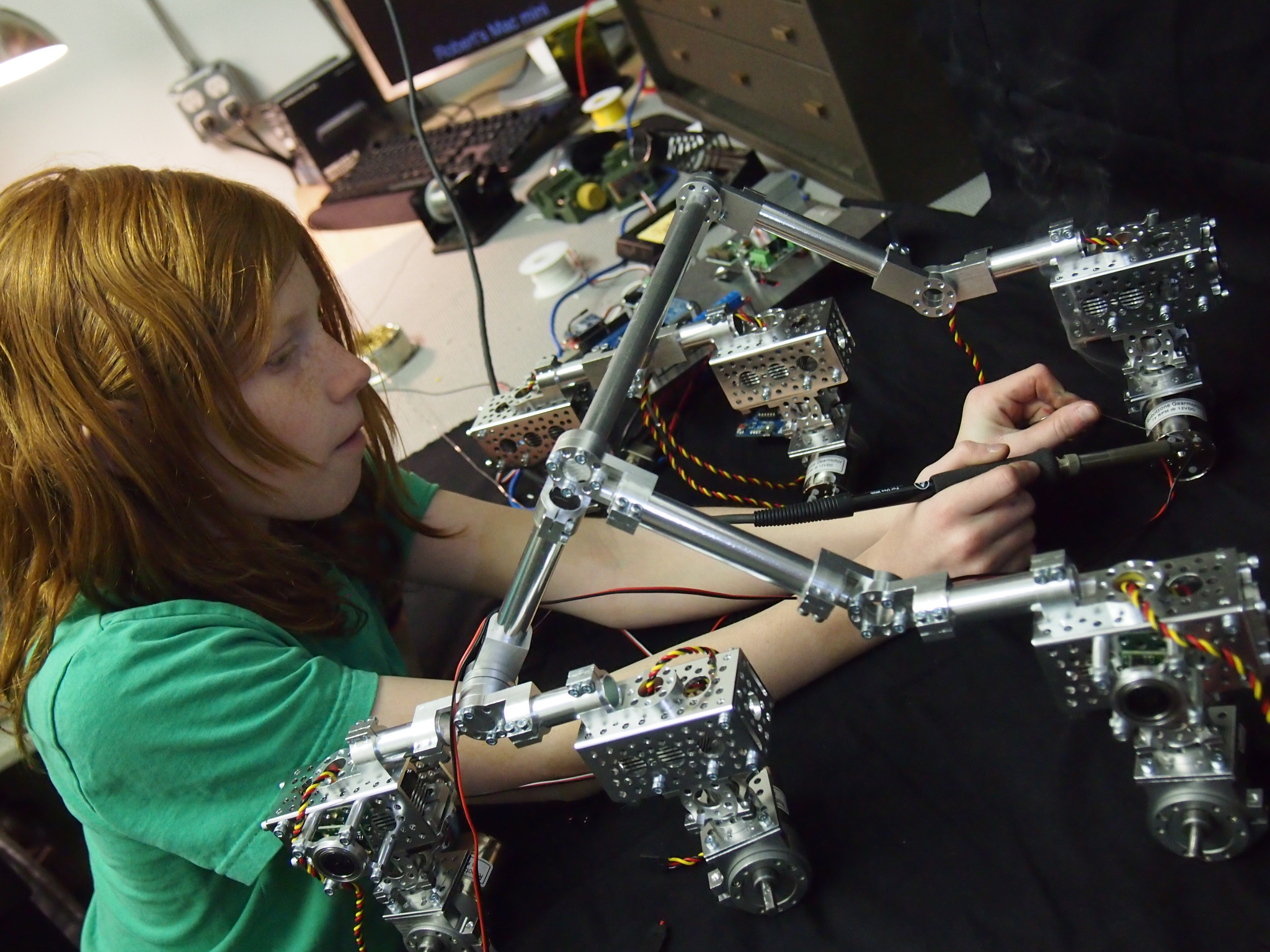
I’m mounting a side-firing sonar sensor on the the rocker-bogie suspension system. She’s done most of the mechanical construction on the robot.
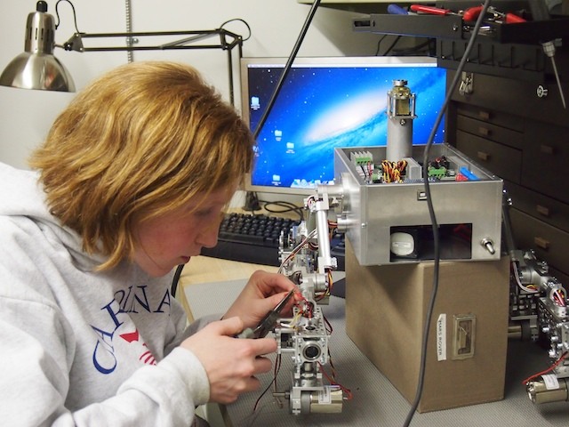
I’m feeding wires through the chassis tube.
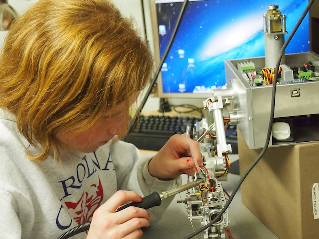
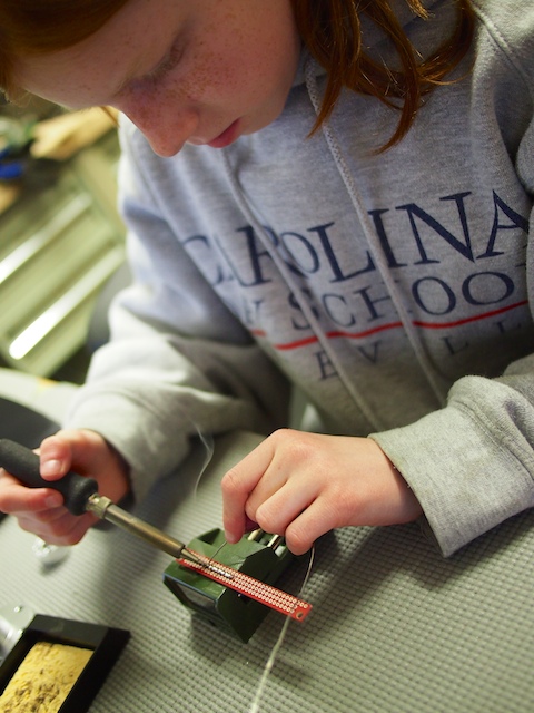
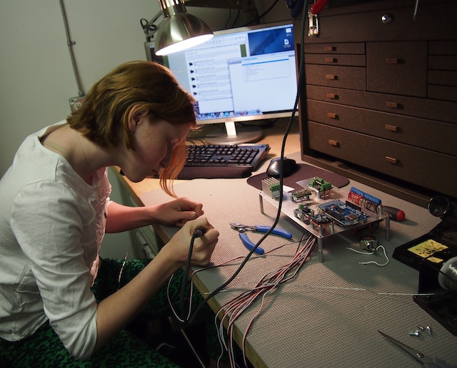
After fishing the wires through the chassis tubes, I solder the power, ground, and signal wires to the sonar sensors.
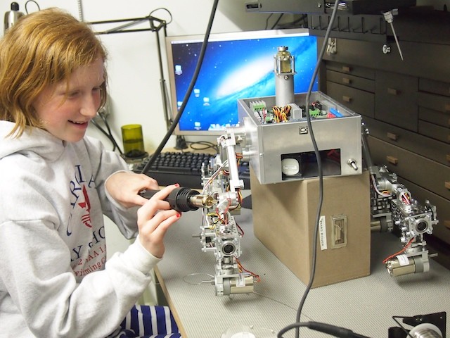
I use the electric heat gun to complete the heat shrinking on the wires she just soldered. (Red nail polish is optional when heat shrinking in our workshop, but always a plus!)
Slowly but surely, we’re making progress. We’ve completed all the wiring and soldering for the sonars, motors, and servos on the chassis, and we’ve assembled and installed the wheels. We sill need to complete the rover’s top, install the solar panels, build the mast head, and many other elements. Stay tuned.
by Camille | Workshop Blog
The Mars Rover needs to detect infrared in its camera so that visitors can identify infrared-emitting rocks that are hidden in various spots in the Mars Exhibit. We have completed a series of experiments to confirm that this part of the Rover is working properly. Pics and explanation below.
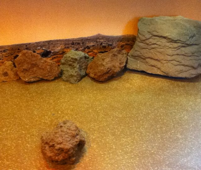
The Mars exhibit has many Mars rocks. A few of the rocks are hollow and have an infrared lamp inside so the rock emits infrared energy. The visitor’s objective is to drive the Rover around the Mars exhibit and find the hidden infrared-emitting rocks. (On the real Mars, infrared-emitting rocks indicate that the rocks may have been formed in liquid water, and therefore may be a clue to past life on Mars)
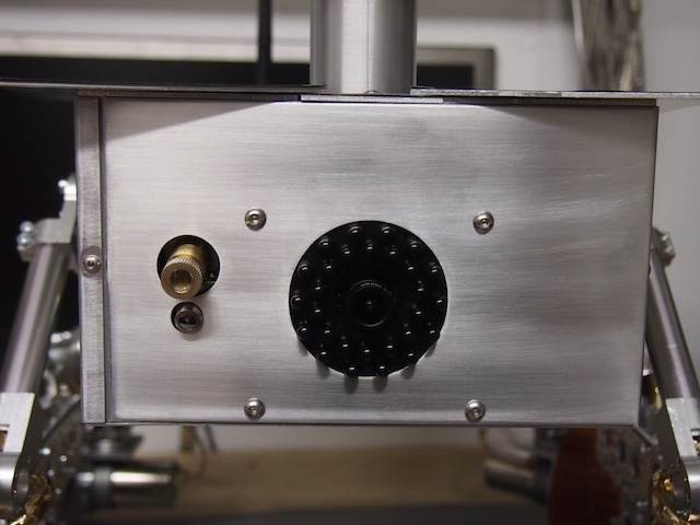
The Mars Rover is equipped with the inner core of a high-quality 640×480 WiFi camera (the Sharx Security SCNC2700). The video camera looks straight ahead from its front panel. By sending the camera a special web-post (thank you to the folks at Sharx for their special help on this), we can programmatically turn the camera’s IR cut-filter on and off, thereby switching the camera between “Normal Camera” mode and “Infrared Camera” mode.
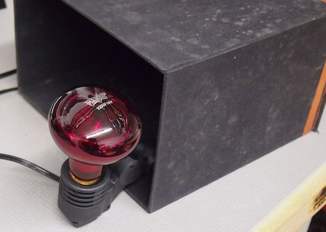
We didn’t have a “Mars Rock” to work with in our workshop, so for this experiment, we placed an infrared lamp inside a black box.
We turned the infrared lamp on.
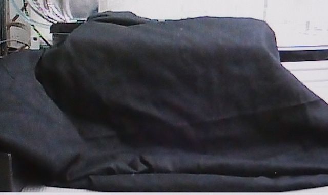
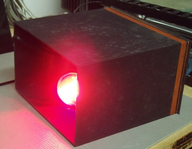
We then covered the box with six layers of black muslin cloth. To the naked eye and when viewing it through the video camera in normal viewing mode it looks simply black. This is serving the purpose of our “Mars Rock” for this experiment. This is a picture of what we see on screen in the camera’s video stream. It looks like normal black cloth.
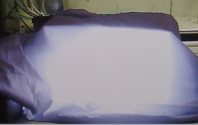
We then turn on the “Infrared Camera” mode. Just as we hoped and theorized, the black box now appears as bright white in the camera. So, when visitors to the exhibit switch the Rover’s camera into “Infrared Camera” mode they will be able to easily differentiate the infrared-emitting rocks from the normal rocks.
Special thanks to the folks at Sharx Security for not freaking out when I told them I was tearing one of their cameras apart piece by piece, integrating it into our robot, and sending it to “Mars.” They were very helpful in providing the technical information we needed to get the camera to do what we needed it to do. All indications are that it’s going to work very well for us.
by Camille | Workshop Blog
We’ve been making good progress on the Mars Rover. Today, we used our new milling machine to put the finishing touches on the hubs we are using to mount the central chassis shaft to the rover’s main box. By completing the two hubs, we were then able to assemble the two sides of the rocker-bogie suspension chassis with the main box, which in turn allowed us to begin soldering the servos and sonar sensors. It’s really starting to come together now. Pictures below.
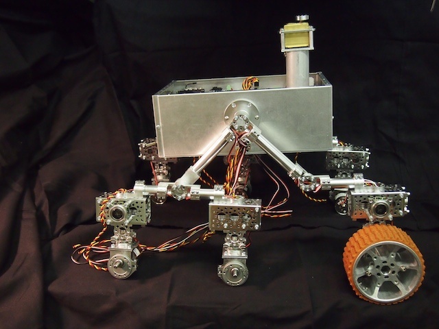
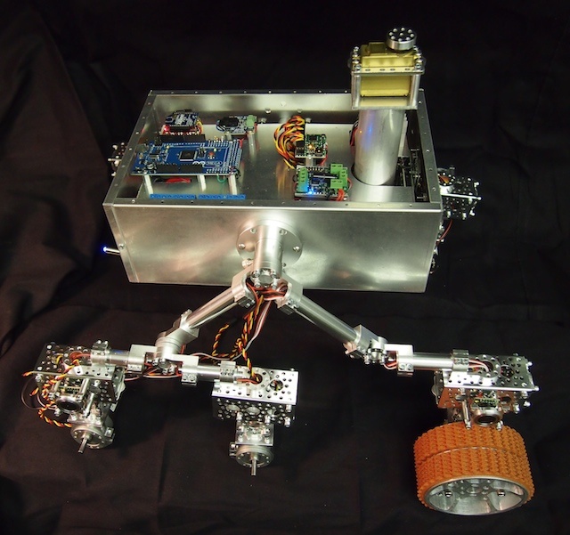
The Mars Rover is starting to take shape. The two sides of the rocker-bogie suspension system have now been installed on the main box. We put one of the wheels in place to show what it will look like. The motor, servo, and two sonar sensors are soldered on the front wheel, but not the back two (thus the hanging wires).
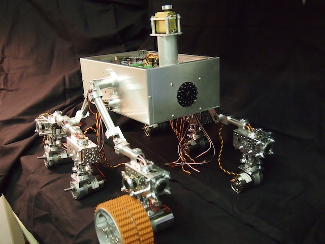
This shot shows the front corner of the partially assembled Mars Rover. Note the camera mounted on the front plate and the partially assembled mast.
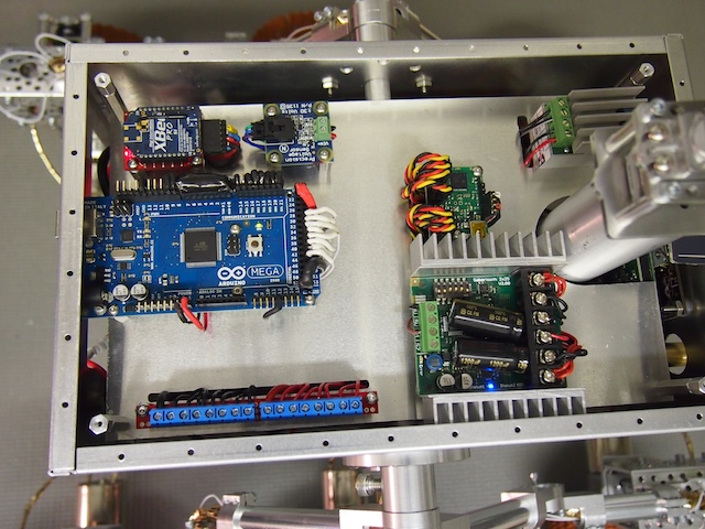
This view provides a glimpse of the electronics inside the main box.
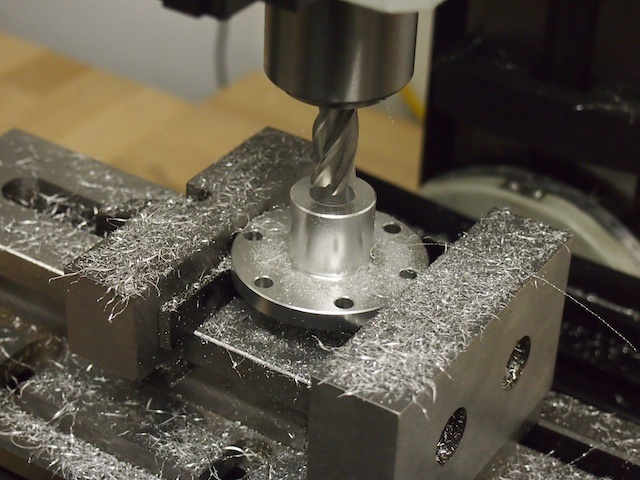
Here we are using our new vertical mill to machine the center hole of the hub.
by Camille | Workshop Blog
A number of folks asked to see an updated picture of the Mars Rover electronics. This picture shows the top most electronics plate where most of the components are mounted. There are also electronics beneath the main electronics plate, including the laser, thermopile array sensor, laser relay and voltage regulator, main fuse, batteries, and main power switch. In addition, the camera is mounted on the front of the rover. In the chassis, there are eight ultrasonic sonar sensors, various resistors and capacitors, six motors, and six servos. There is a seventh servo in the mast head.
Mars Rover – Main Electronics Plate – From left to right, top to bottom: xbee radio, voltage sensor, voltage booster for camera, Arduino Mega, servo controller, power rail and motor controller.
by Camille | Workshop Blog
We’ve been making great progress on our new Mars Rover. We’ve posted some pics below.

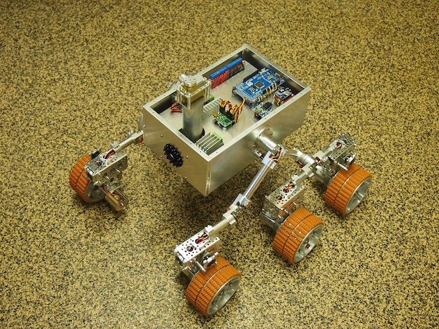
We have completed the hardware portion of the rocker-bogie suspeƒnsion system for the new Mars Rover, which is by far the most challenging portion of the build. This new chassis is far superior to the previous version in terms of robustness. Also, the black circles at the corners are sonars. Each corner wheel has two sonars (one pointing to the side and the other pointing either forward or backward). This rover will be able to detect exactly how close it is to all the obstacles around it, such as rocks and walls.
Building a sonar sub-assembly.
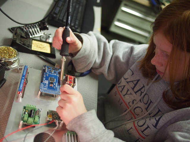
Genevieve is soldering the various components to the Arduino Mega microcontroller.
Genevieve building the Power Distribution Rail. We call this “making caterpillars.”
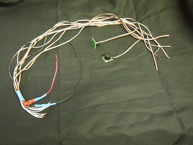
The three of us worked together to build this special wiring harness that will provide power and connect the 8 sonars to the main Arduino board. We call this “the squid.”
Genevieve soldering the wires onto the motors.

Genevieve working on the electronic elements of the chassis.
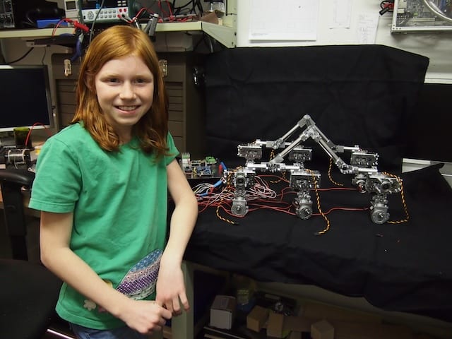
Genevieve in front of the Mars Rover chassis
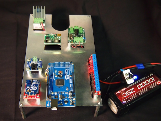
The Mars Rover electronics, powered up with a 7.4V battery.

The underside of the Mars Rover electronics plate.
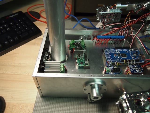
The electronics plate mounted inside the main box. You can also see the chassis hub on the side, the camera mounted in the front, and the mast.
