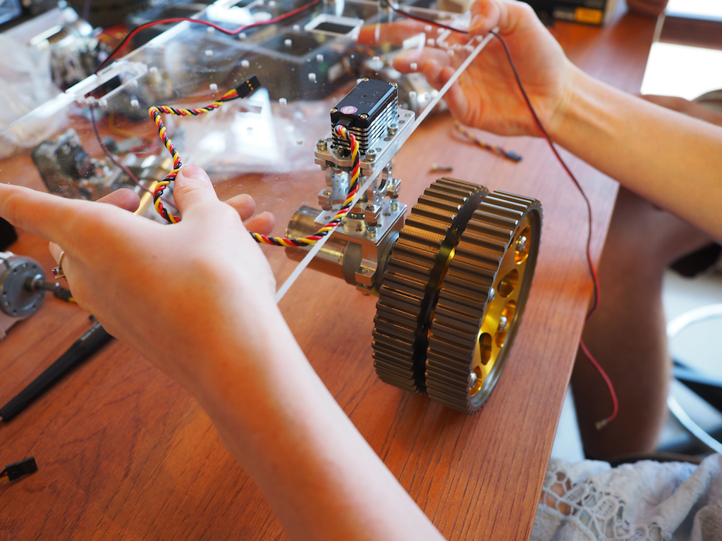
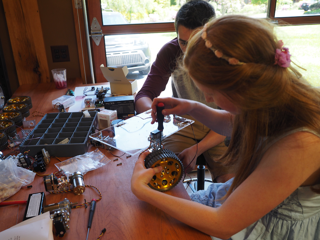
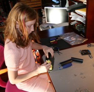
We have taken on a new project to build a compact rover for the New York Hall of Science, something that visitors can drive around in the corridors of the Science Center and that the staff can easily take to off-site activities such as schools and children’s hospitals. The design and construction is well under way. We are also happy to announce that we have a new member at Beatty Robotics. His name is Camille McCollough. He’s a junior at Carolina Day School, where he is taking robotics classes, as well as physics, math, and other curriculum. He has joined our team to learn, gain experience, and lend a hand. Here is Camille building the robot’s pan-tilt turret from Actobotics parts, including a servo, gearbox, and gears:
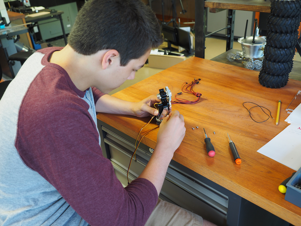
Camille and Camille working on the assembly of the robot’s front LED “head lights”:
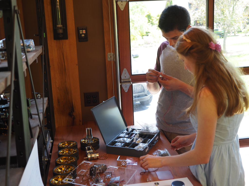
Camille working on the assembly of the sonar mounts, while Camille works on the pan-tilt turret:
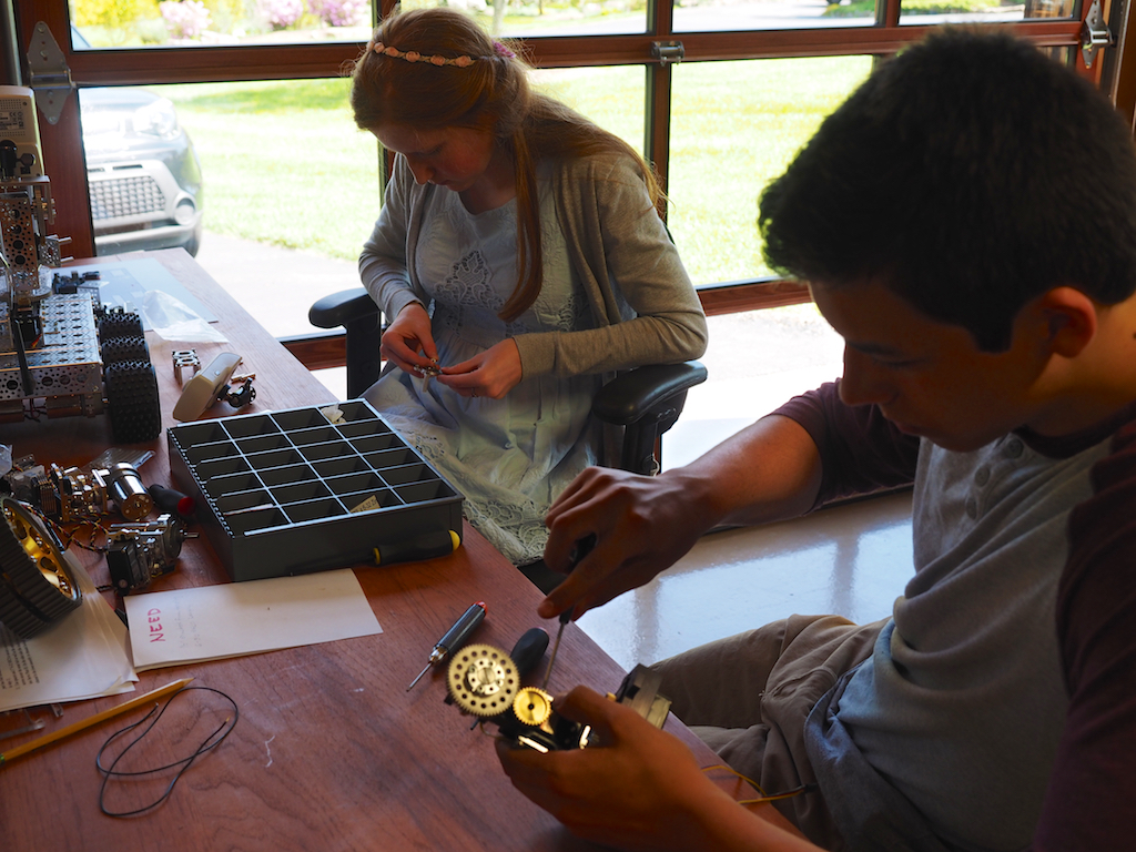
Camille building the first of the six steering assemblies, each of which consists of a servo, servo block, motor, hub, and wheel. We are using a combination of Actobotics parts and our own parts that we made on the CNC.
Camille tests the design and assembly of the first steering servo and wheel.
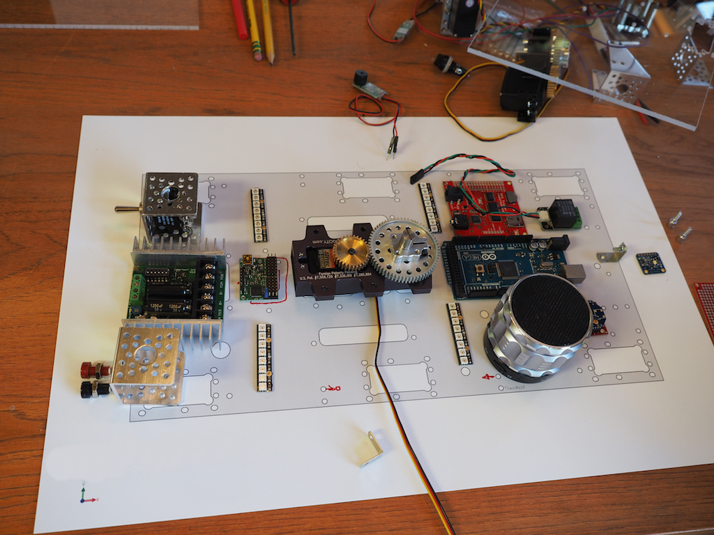
We use a scale drawing of the master plate to plan out where all the components are going to be positioned.
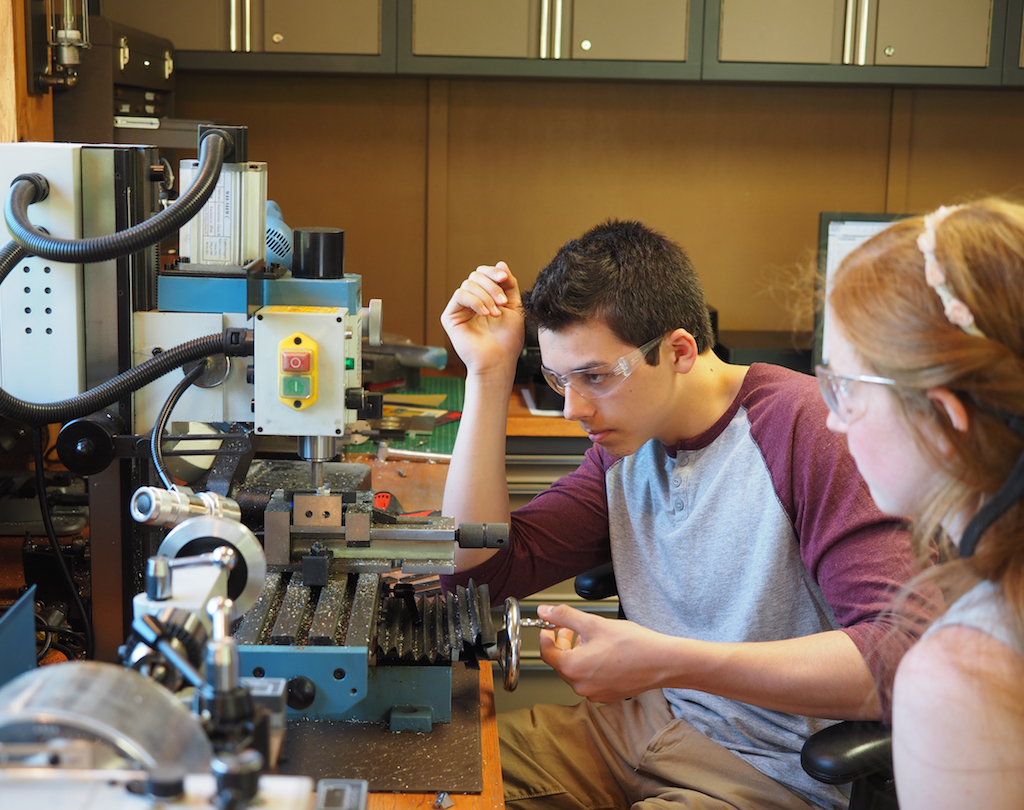
Camille shows Camille how to machine a part of the vertical mill.
Camille machines the next part on the vertical mill.
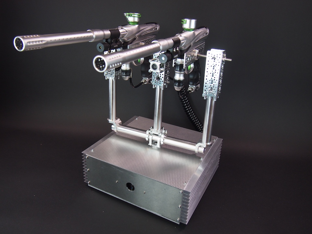
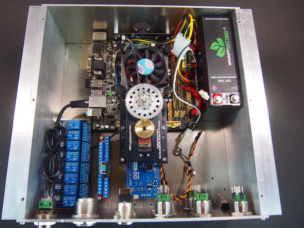
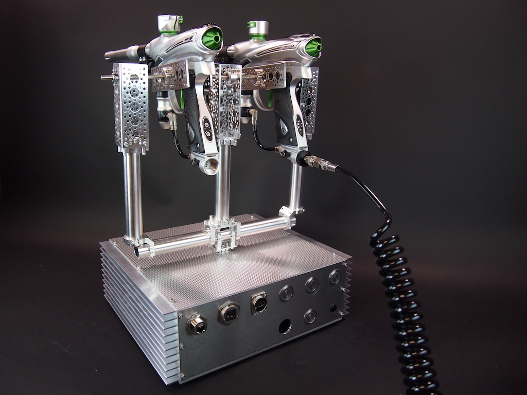
The Centurion is an automatic-targeting paintball sentry gun. Its purpose is to guard a doorway, alleyway, or any open space. It watches an area with its camera. If it sees movement, it aims its guns at it and shoots at a high rate of fire until the target leaves the field of view or stops moving. As long as the target keeps moving, the guns track the movement and keep shooting. It can also differentiate color. So, for example, team members with blue sweat shirts could be allowed to pass, but enemies with red sweatshirts will be dealt with severely. The main components are:
Motherboard with a Corei5-4570S Quad Core 2.9Ghz, 8GB RAM, 120GB SSD, & WiFi module
Arduino Leonardo
Wide-angle HD webcam
8-Channel Relay Board
12v 7,000mAh Lithium-Ion battery
Actobotics Pan-Tilt Turret
Actobotics tubes, channel, brackets, clamps, shafts, ball bearings, gears, and other components
Actobotics Hitec Servos
Maxbotix ultrasonic range finder
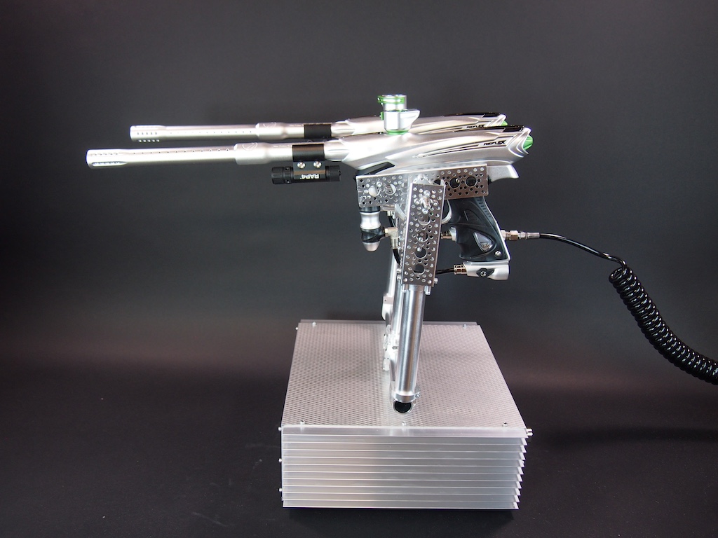
(2) high-performance paintball guns (Dye Proto Reflex 14’s with custom modified barrels)
(2) targeting lasers
(2) electric ammunition hoppers (not shown)
(2) air tanks (not shown)
Portable keyboard, mouse, and keyboard (not shown)(not necessary for operation)
We started out with the code from the open source Project Sentry Gun, which is written in Processing, and then went from there.
The Centurion is one of several projects that we work on just for fun when we aren’t working other projects. The whole system isn’t done yet, but we’ve made good progress on it. We are currently working on two new projects for the New York Hall of Science, so we won’t be getting back to this one for a while, but we thought we would share our work-in-progress.
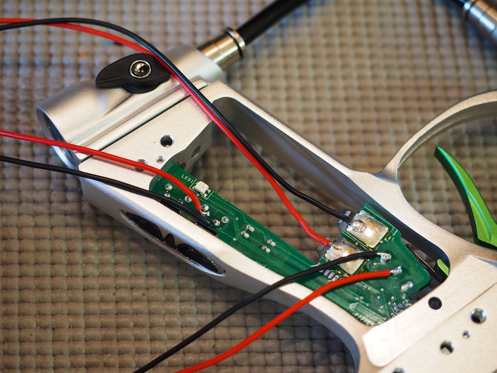
We hacked into the circuit board of the paintball guns in order to load and fire the guns electronically.
We reverse engineered the gun’s circuit board to figure out where we needed to hack into it in order to control the firing sequence.
We built an aluminum enclosure for the electronics and the base of the pan-tilt turret, which is made with Actobotics hardware and servos:
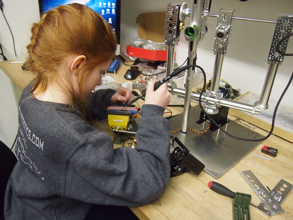
Genevieve wiring up the relay board, which will control the firing of the paintball guns. Is that a gentle smile or a devilish grin? Is she thinking about paint balls flying at anyone in particular?
Genevieve soldering the power distribution board.
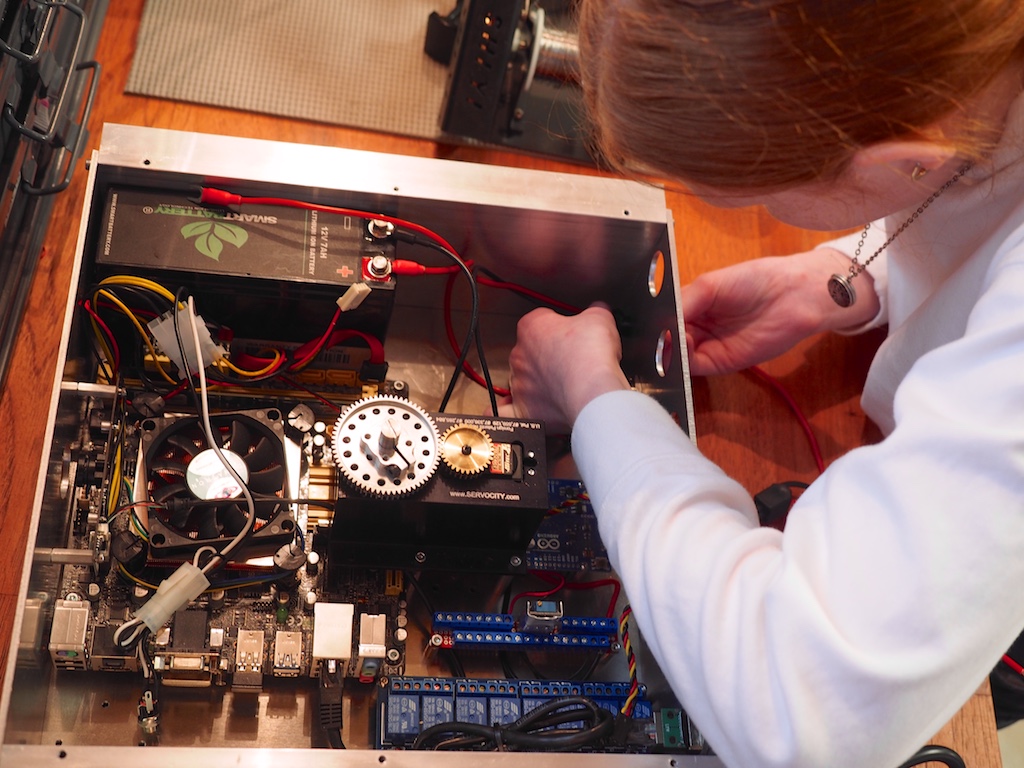
Genevieve wiring up the control switches and buttons on the back of the electronics enclosure.
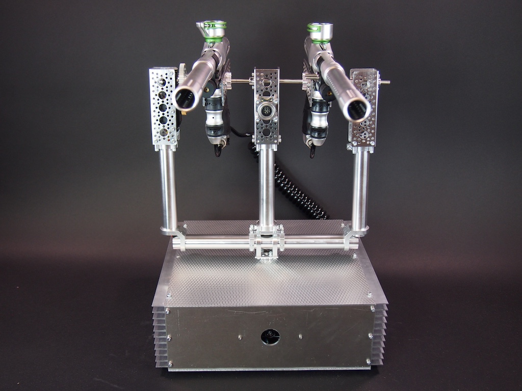
Back view of the Centurion Sentry Gun, including multiple jacks and push buttons:
Front View, including the front port that the camera looks out of. When we are done, the port will be covered in glass.
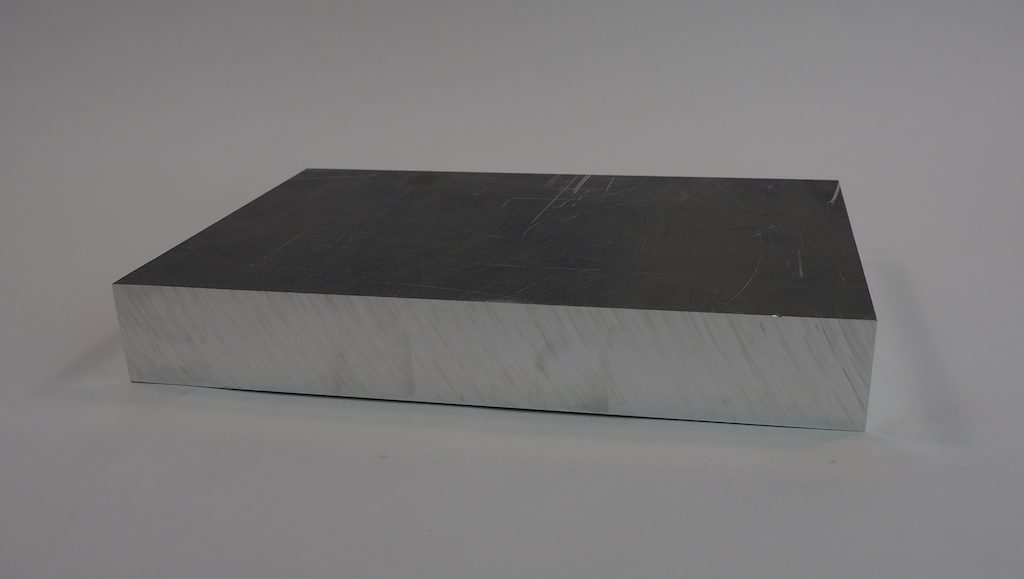
We’ve been working on a fun new robot we call Metalbot. Our goal was to build an autonomous rover with a unibody design that was machined out of a single block of metal. We started with this 13” x 9” x 1.75” block of 6061 aluminum:
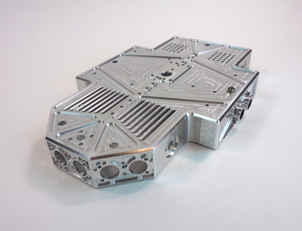
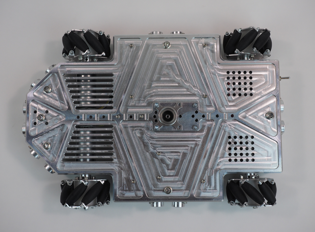
When the machining was done, the robot’s body looked like this. It’s a hollowed-out shell that is about 1/8” thick with holes, slots, and pockets for the motors, LEDs, sensors, and other electronics.
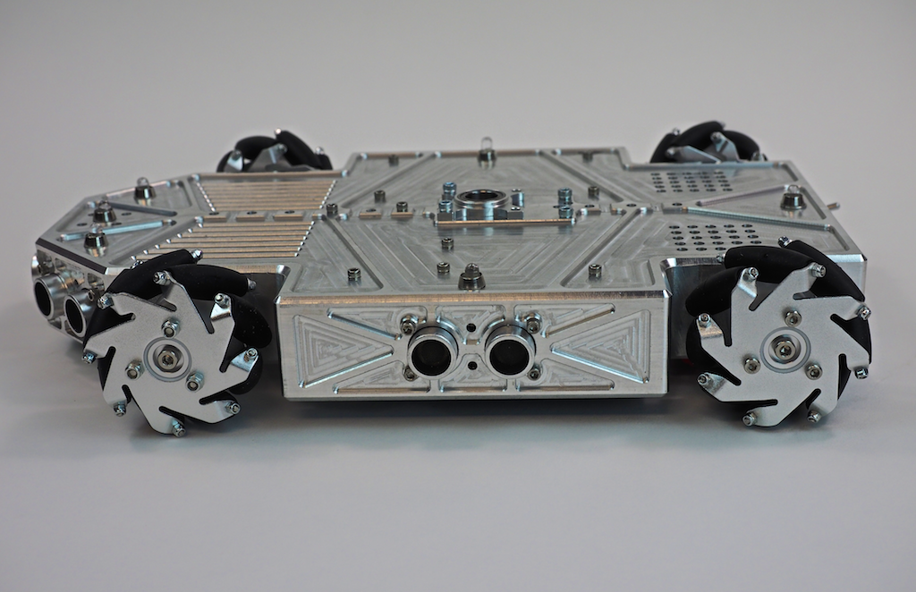
Once Metalbot was assembled with the internal components, it looked like this:
What do you think? We think it’s pretty cool looking. Do you like it?
Work-in-Process Pics
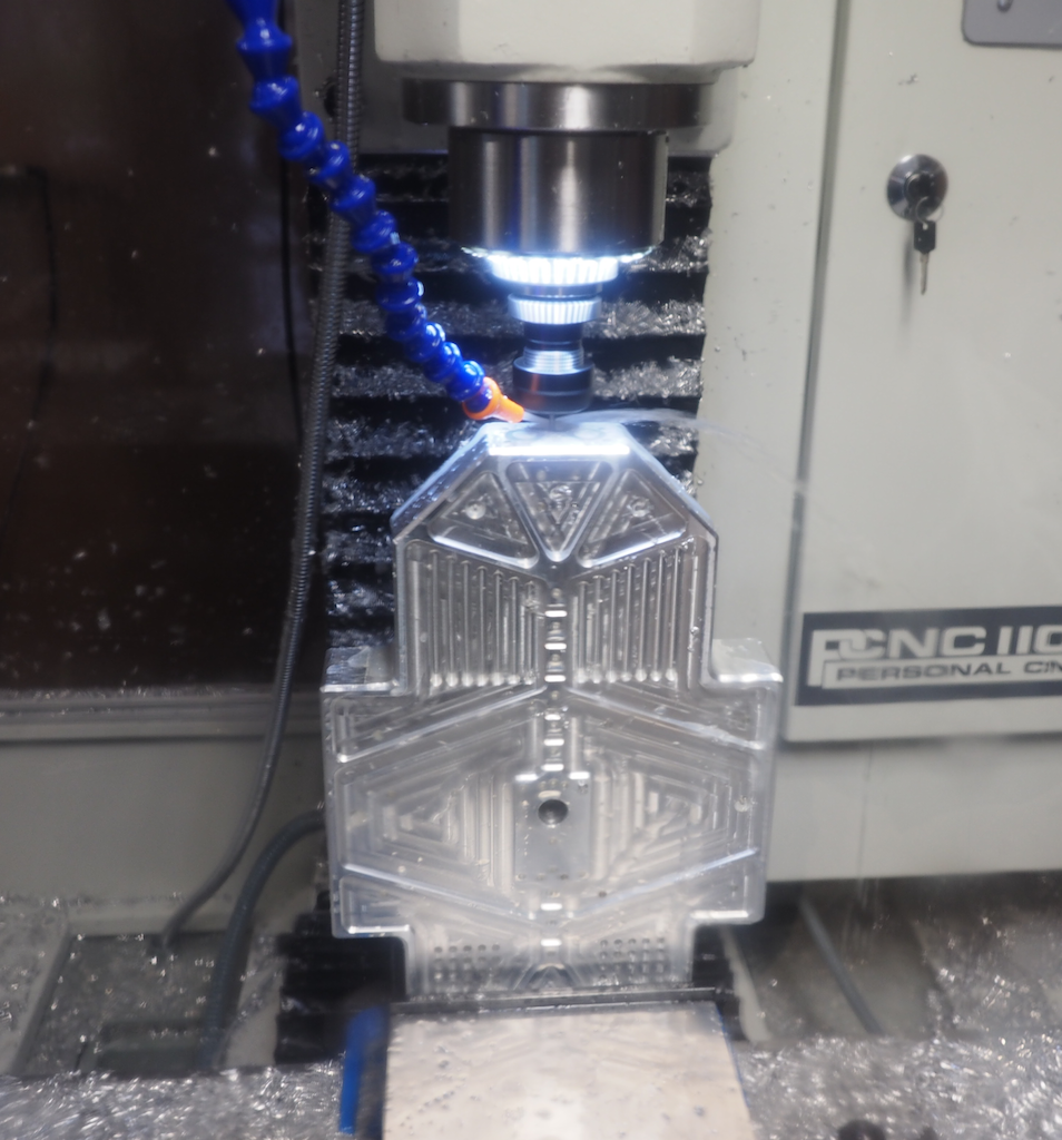
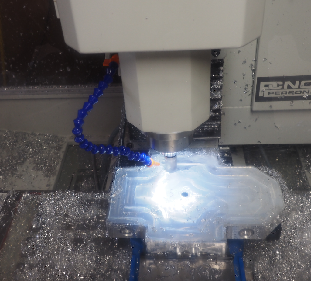
In this first picture (which was taken through the polycarbonate enclosure), we clamped the part vertically in the vise and we’re using an 1/8″ end mill to machine the detail on the front of the nose. In a previous operation we clamped the stock flat and machined the top of the robot, so that work is already done. Because this part has features on every side, machining it required us to clamp the stock in the vise in 8 different orientations: top, left side, right side, back, front, 45-degree left nose, 45-degree right nose, and bottom.
In this next picture, we’re on the last setup, machining out the large pocket on the underside of the robot. This turned the aluminum block into a 1/8” thick shell. The large pocket appears to be glowing because the ring of LEDs we installed around the mill’s spindle are shining into the coolant that has filled the pocket. We’re using a 25mm (.98”) modular end mill here, which is designed to remove material fast. Of course, there were a lot of metal chips, but it’s important to remember that aluminum is easy and efficient to recycle.
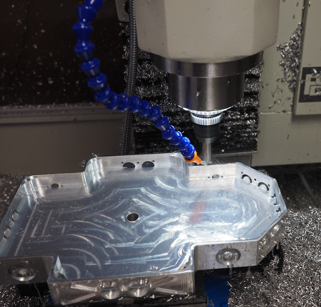
In this picture we’re half way done digging the pocket and we have the machine take a break from the hard work to chamfer the outside contour:
Once the body is machined, we screwed in the wheels, motors, and electronics, which are screwed upside down on the underside, where they are easy to access when the robot is turned over. We will install a bottom plate later.
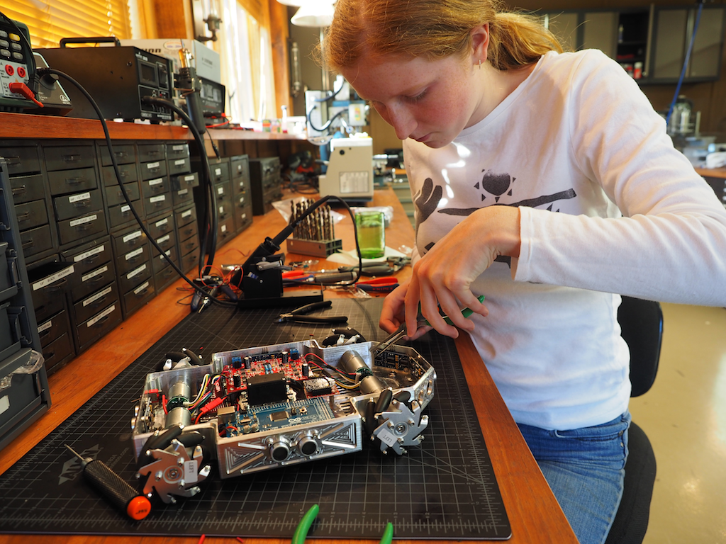
Then we did the wiring and soldering:
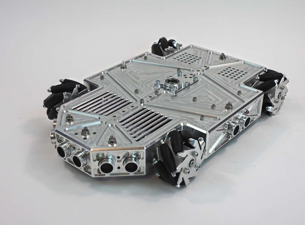
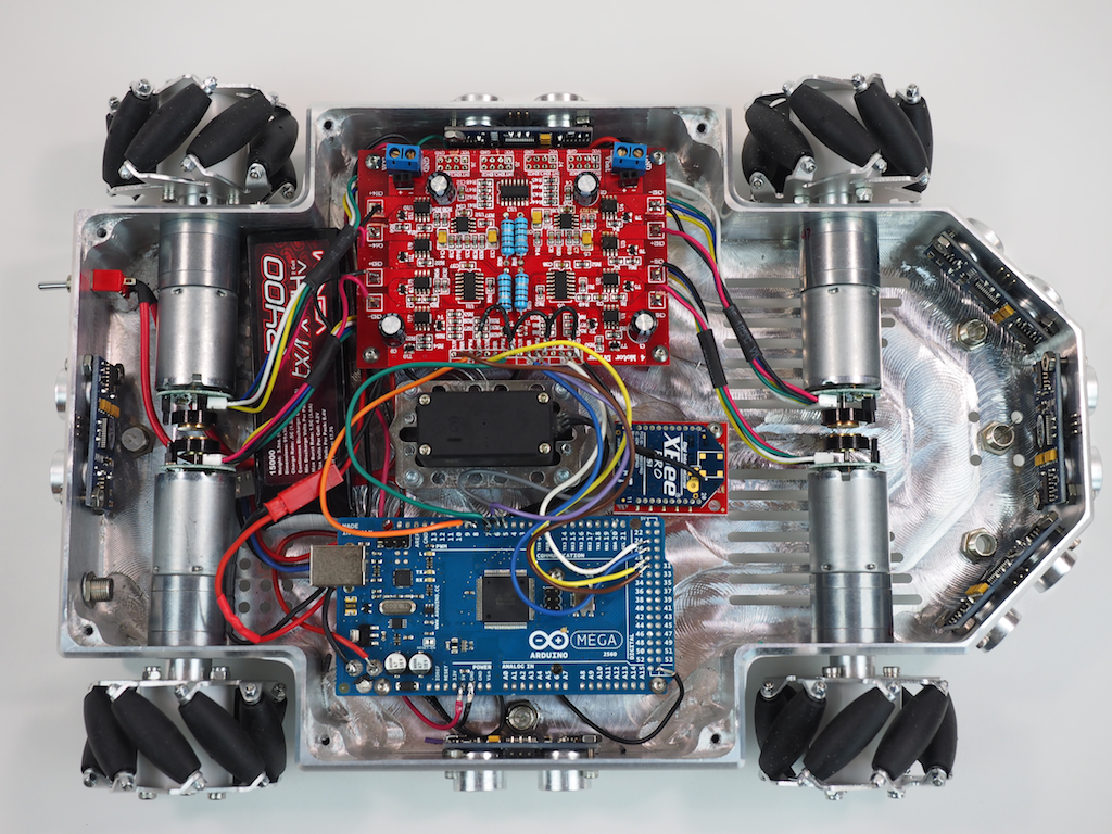
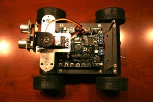
Here is the underside of the robot with most of the electronics installed. We’re using an Arduino Mega and a 4-channel Motor Controller, along with 4 Pololu gear motors to drive the mecanum wheels, which will allow the robot to strafe. The robot is also equipped with 6 Ping ultrasonic sensors for autonomous object detection, a LIPO battery, a main power switch, 6 NeoPixel RGB LEDs to indicate the state of each sensor, an Xbee Radio, and a panning servo (black thing in the middle). The robot will also be equipped with an MP3 module and speaker for sound, but those haven’t been installed yet.
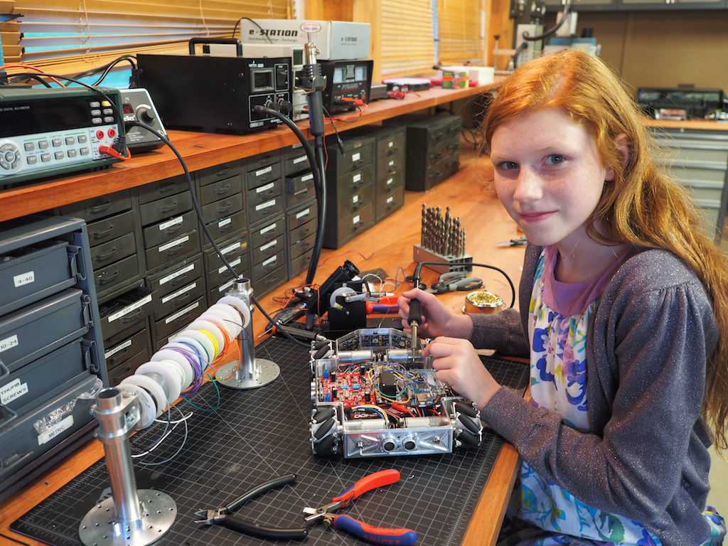
The robot’s finished body is 8” wide and 12” long. The rover can be fitted with either the mecanum wheels shown or CNC-machined conventional wheels (not shown). Our original goal was just to machine a cool looking rover out of a single piece of metal, but as we went along, we decided to add some flexibility into the design for future enhancements in case we wanted to do more with it. The robot has been designed with a central spine of holes and ridges for attaching future add-ons, including a servo mounted in the center, which will support a pan-tilt turret for a camera, gun, or arm. We have designed the pan-tilt turret to utilize the Actobotics ecosystem, but other pan-tilt mechanisms could also be used. There are also holes on the front and rear of the top deck that are compatible with the full range of Actobotics components such as brackets, hubs, and channels, which really adds a lot of flexibility.
The next step is to work on the sensors and software programming. With its mecanum wheels, it should be able strafe like a champ very soon.
Here are a few more pictures of Metalbot so far. Let us know what you think. Do you like the overall design?
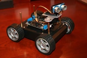
Today, we would like to introduce Terrabot, our Terrain Traveling Robot. Based on a modified “rock crawler” chassis, its primary purpose is to traverse rocks, branches, steep slopes, flower beds, boulders, mountain trails, and other extremely rough terrain.
Terrabot
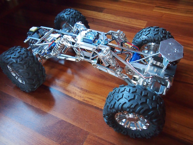
Terrabot is equipped with 4-wheel steering (4WS). Two high torque servos shift machined aluminum linkages to rotate its front and back wheels independently. Note the navigation GPS on top of the back servo (on the left) and the sensor turret on the front (right). Terrabot’s four wheels are driven by two powerful brushless motors (bright blue) and robust gearboxes (centered in each axle).
Terrabot’s highly-articulated chassis is designed to twist up to 90 degrees as the robot is moving, allowing it to climb over huge boulders and other obstacles. In this picture, the chassis is articulated 45 degrees. Note that the back tires are still on the ground because the center linkages of the bot are twisted.
Terrabot’s topside electronics include a tiny Arduino Nano (lower left), an XBee Radio (right), and a 9-DOF Mongoose Inerntial Measurement Unit (IMU). The IMU measures the degree of tilt and the rate of acceleration in the X, Y, Z planes, which we plan to use for our stabilization algorithm.
Terrabot’s other electronics are stuffed into the little chamber inside the aluminum core (note the blue LED at the bottom of the picture). This includes the two Electronic Speed Controllers for the motors, the Pololu Maeastro motor/servo controller, the power rails, various voltage regulators, and other electronics. The navigation GPS (see the first picture), is mounted on top of the rear servo so that it has a clear view of the sky.
Terrabot Side View, showing the shocks, the frame, and LIPO battery beneath. Note the “roll posts” we installed on the top to protect the topside electronics if Terrabot falls off a rock during a climb and flips over. (We learned this one from experience!)
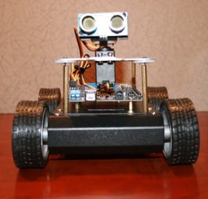
Terrabot Front View. There are three sonars mounted in the sensor turret, which rotates 270 degrees when the robot “looks around” to determine the best course through obstacle-ridden rough terrain.
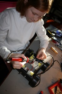
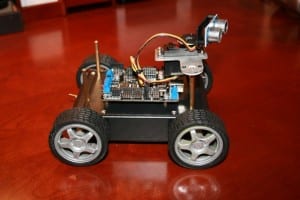
We have had a number of friends and family members ask how they can get started in robotics. They are interested in building a robot, especially a vehicle of some sort, but they don’t know where to begin. So, we have been working on the design for a small, inexpensive, easy to build, multifunctional, Arduino-based, programmable robot that will require basic robot building skills, but nothing too fancy. We call it “KitBot.” Our hope is to be able to help people get started. It will be able to function autonomously, but also by RC. It will include many off-the-shelf parts, a basic rover design, motors, servo, sonar sensor, sound, LED lights, and so on. These are our first pictures, which show the beginnings of the initial test project. It’s not done yet, but you can see the direction we’re moving. We have also sent all the parts to build a KitBot to a father and son team to be our initial Guinea Pigs (they wanted to try building it for a school project). As we work on refining the design and features, we’ll see how the father-and-son team does with the initial construction.
Soldering the power wires to the KitBot’s motorsAssembling our KitBot chassisKitBot: Top ViewKitBot: Corner ViewKitBot: Front ViewKitBot: Side View