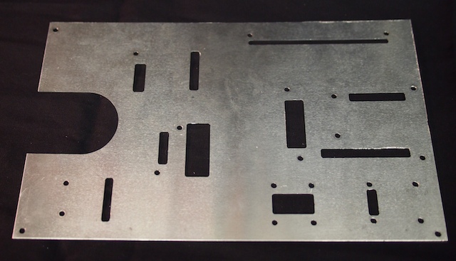
Here we are using our homemade CNC to machine a custom electronics plate for the new Mars Rover we’re building. The robot’s circuit boards and electronic components are mounted onto this plate, which is then mounted inside the robot’s main box. Check out the video and the photos below.
The completed electronics plate for the Mars Rover.
Here is the electronics plate with the various circuit boards and other electronic components mounted. Wiring and soldering comes next. The wires will go through the rectangular holes underneath each circuit board and then run beneath the plate.
We are working everyday on the new Mars Rover. The work is going so fast that it’s hard to remember to take pictures, but here are some of the pics we snap along the way.
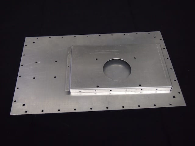
We cut these hole patterns for the Mars Rover’s Front and Bottom Plates using the CNC.
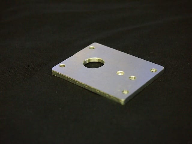
We also used our CNC mill to make this custom Servo Plate for the Mars Rover’s mast. We design all our parts in the SolidWorks CAD system.
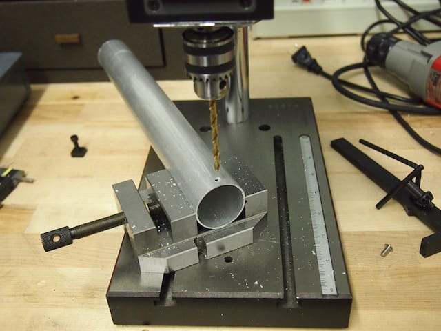
There are also times when we need to do it the old fashioned way. Here we are drilling a bracket hole in the Mars Rover mast, which is a 1.5″ aluminum hollow tube.
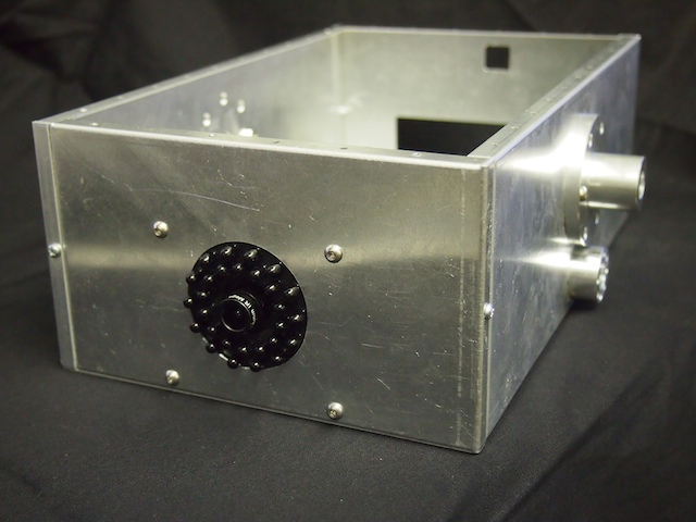
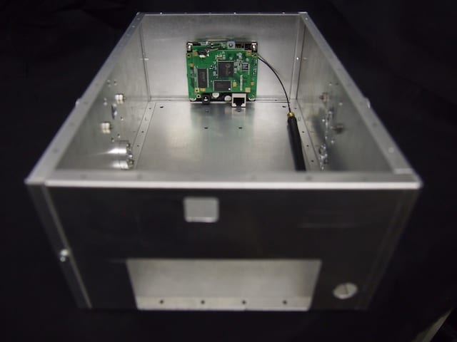
Here is the inside of the assembled Mars Rover box with the camera mounted in the front panel.
Here is the assembled Mars Rover box showing the camera mounted on the front panel. The black protrusions are IR LEDs for night vision capability.
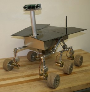
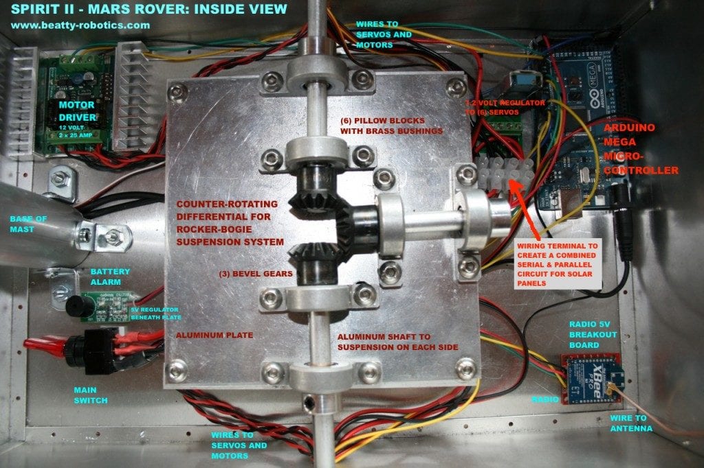
Several readers have requested an inside view of our Spirit II – Mars Rover so that they can see what the electronics look like. We have provided an annotated picture below, along with a couple of external shots.
My sister Genevieve is an expert solderer. Her hands are small, steady, and well practiced. Here is a picture of her soldering a voltage regulator for our Spirit II Mars Rover project.
Genevieve soldering
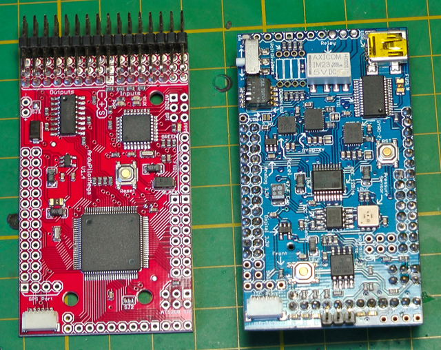
Here is a one minute video of Genevieve soldering the header pins onto a circuit board. We use this circuit board, which has more than a hundred solder points, on our flying drone robot. Note that she is using the proper technique by applying the tip of the soldering iron to the pin and hole, then bringing in the solder from the side.
CREDITS:
Solderer: Genevieve (9 years old)
Director & Videographer: Camille (11 years old)
Editing: Camille, Genevieve, and R.
We have been hard at work on our latest project called Mechatron. To control our Mechatron robot as well as our Mars Rover, we designed and built our own remote control box. We developed our own communication protocol for transmitting commands from the remote control to the robot. On other projects we used iPhones and Playstation remote controllers, but in this case we wanted to build a large, metal box with lots of retro-switches and joysticks.
1. Although it wasn’t cheap, the hall-effect 3-axis joystick was critical for controlling the function of Mechatron’s specialized drive system. We originally tried a traditional analog/resistive/potentiometer-style joystick and it did not work well at all. We thought our whole project was going to fail until we realized that not all joysticks are created equal. The joystick based on the “hall-effect” principle worked perfectly for us.
2. You can’t see it in these photos, but this controller can be charged via banana jacks and re-programmed via a USB jack without having to unscrew and remove the case. The same is true for the Mechatron robot itself.