by Camille | Workshop Blog
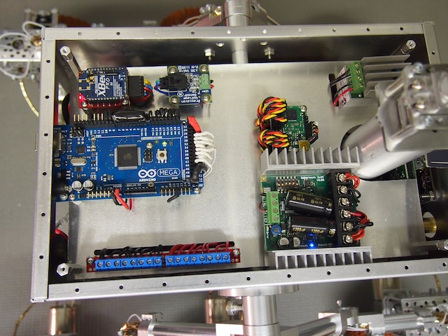
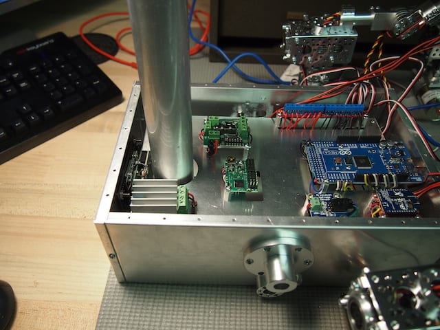
A number of folks asked to see an updated picture of the Mars Rover electronics. This picture shows the top most electronics plate where most of the components are mounted. There are also electronics beneath the main electronics plate, including the laser, thermopile array sensor, laser relay and voltage regulator, main fuse, batteries, and main power switch. In addition, the camera is mounted on the front of the rover. In the chassis, there are eight ultrasonic sonar sensors, various resistors and capacitors, six motors, and six servos. There is a seventh servo in the mast head.
Mars Rover – Main Electronics Plate – From left to right, top to bottom: xbee radio, voltage sensor, voltage booster for camera, Arduino Mega, servo controller, power rail and motor controller.
by Camille | Workshop Blog
We’ve been making great progress on our new Mars Rover. We’ve posted some pics below.

We have completed the hardware portion of the rocker-bogie suspeƒnsion system for the new Mars Rover, which is by far the most challenging portion of the build. This new chassis is far superior to the previous version in terms of robustness. Also, the black circles at the corners are sonars. Each corner wheel has two sonars (one pointing to the side and the other pointing either forward or backward). This rover will be able to detect exactly how close it is to all the obstacles around it, such as rocks and walls.
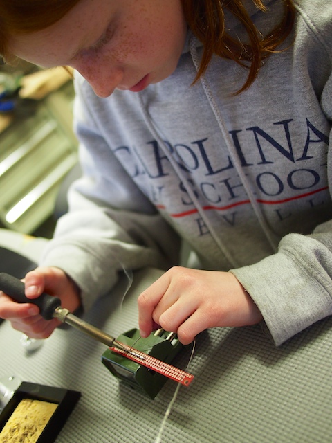
Building a sonar sub-assembly.
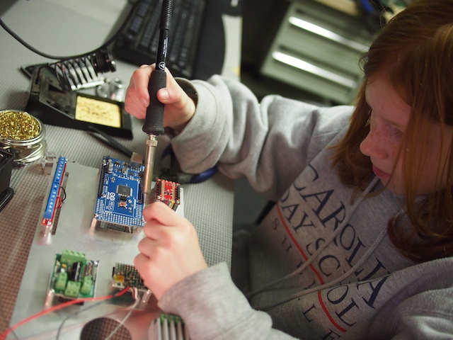
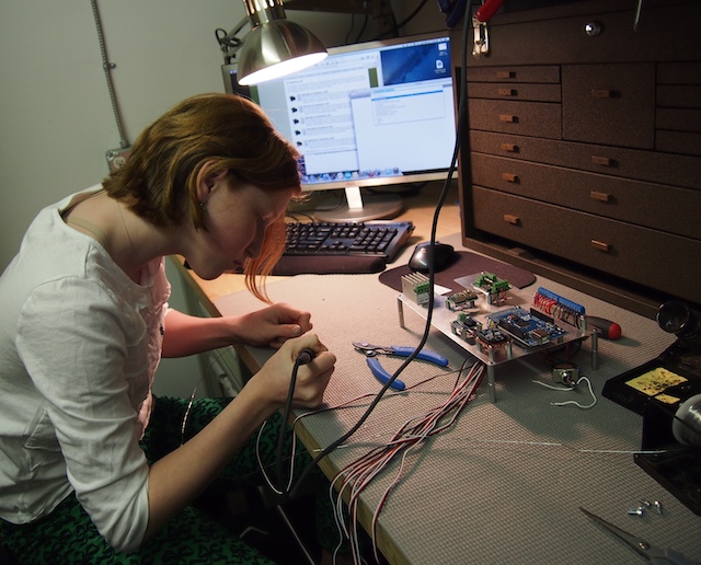
Genevieve is soldering the various components to the Arduino Mega microcontroller.
Genevieve building the Power Distribution Rail. We call this “making caterpillars.”
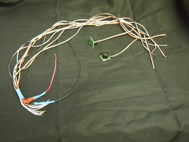
The three of us worked together to build this special wiring harness that will provide power and connect the 8 sonars to the main Arduino board. We call this “the squid.”
Genevieve soldering the wires onto the motors.

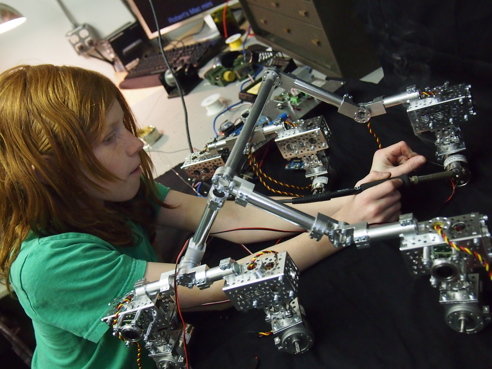
Genevieve working on the electronic elements of the chassis.
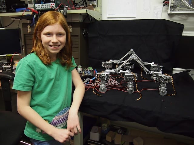
Genevieve in front of the Mars Rover chassis
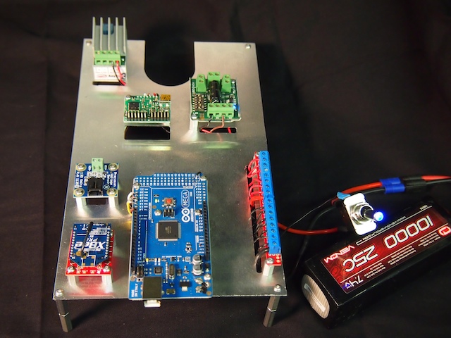
The Mars Rover electronics, powered up with a 7.4V battery.

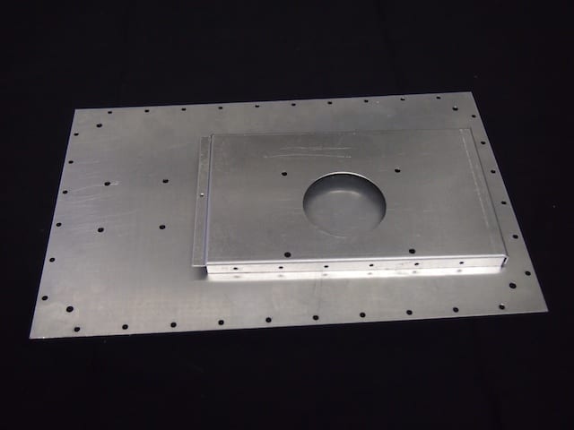
The underside of the Mars Rover electronics plate.
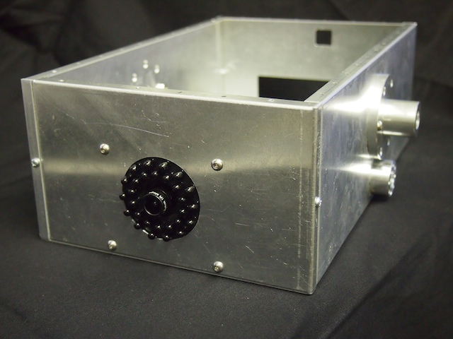
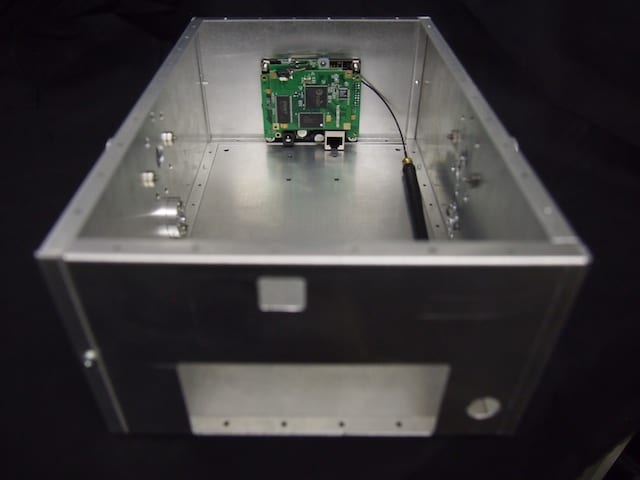
The electronics plate mounted inside the main box. You can also see the chassis hub on the side, the camera mounted in the front, and the mast.
by Camille | Workshop Blog
Here we are using our homemade CNC to machine a custom electronics plate for the new Mars Rover we’re building. The robot’s circuit boards and electronic components are mounted onto this plate, which is then mounted inside the robot’s main box. Check out the video and the photos below.
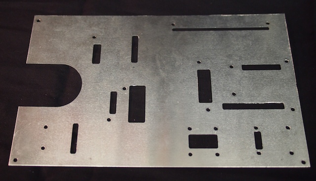
The completed electronics plate for the Mars Rover.

Here is the electronics plate with the various circuit boards and other electronic components mounted. Wiring and soldering comes next. The wires will go through the rectangular holes underneath each circuit board and then run beneath the plate.
by Camille | Workshop Blog
We are working everyday on the new Mars Rover. The work is going so fast that it’s hard to remember to take pictures, but here are some of the pics we snap along the way.
We cut these hole patterns for the Mars Rover’s Front and Bottom Plates using the CNC.
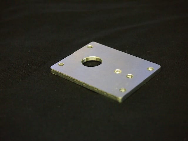
We also used our CNC mill to make this custom Servo Plate for the Mars Rover’s mast. We design all our parts in the SolidWorks CAD system.
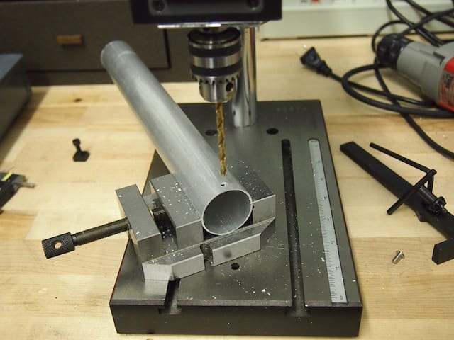
There are also times when we need to do it the old fashioned way. Here we are drilling a bracket hole in the Mars Rover mast, which is a 1.5″ aluminum hollow tube.
Here is the inside of the assembled Mars Rover box with the camera mounted in the front panel.
Here is the assembled Mars Rover box showing the camera mounted on the front panel. The black protrusions are IR LEDs for night vision capability.
