by Camille | Gallery, Robots, Slider, Workshop Blog
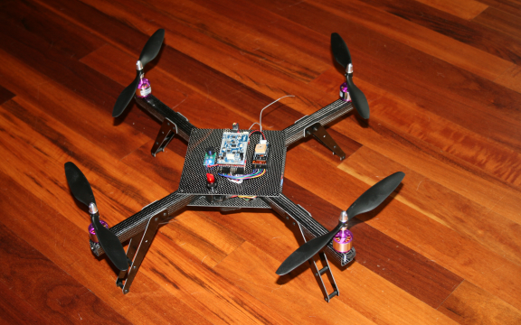
Today, we would like to introduce Black Dragon, our newest flying robot quadrotor. This newest flyer incorporates everything we’ve learned to date about ease-of-use, modular maintainability, crash resistance, lightness, and safety. While we constructed all our previous full-sized quadrotors with aluminum, we designed and built this new flyer with super-cool carbon fiber material. This particular type of carbon fiber, which carries the brand-name “Dragon Plate” (www.dragonplate.com), is used in the aerospace and defense industry, among others. It’s very light, very strong, looks fantastic (the photos don’t do it justice), and is surprisingly machinable.

BLACK DRAGON: Our first carbon fiber quadrotor

Our CAD drawing for the Black Dragon frame design

Our Carbon Fiber Frame

Carbon Fiber Arm. Note that we drilled the motor holes and landing gear holes directly into the arm in order to reduce parts
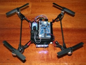
Like our previous quadrotors, we are using the Arduino-based ArduPilot Mega board as the main controller, a 3-axis Inertial Measurement Unit shield (IMU), a GPS for autopilot navigation, Magnetometer for heading control, and a Sonar for altitude control. The robot can be flown via an RC controller or on various autopilot modes. New features include a large illuminated toggle switch for easy on/off in the field, large main plates to hold electronics and wires, improved frame design, complete elimination of the motor mounts (which used to be susceptible to bending), an x-oriented frame (as opposed to +) to provide an open field of view for a camera mounted on the the front, and improved landing gear.
The carbon fiber material is excellent. We love it. It’s easier to machine and work with than we expected (even with the necessary safety precautions), it’s very attractive, but best of all it’s both very light and very strong. For example, the previous aluminum arms weighed in at about 50 grams each. The new arms are 21 grams each. The whole unit ways in at about 850 grams without the LIPO battery.

Close up view of some of Black Dragon’s electronics
We’ve loaded the software into the microcontroller, calibrated the ESC/motors, double-checked the prop rotation, tested the sonar, set the magnetic declination on the magnetometer, confirmed the GPS is giving good long/lat, and it’s ready to fly. We’ve flown it a few inches off the floor indoors just to make sure it’s good-to-go and so far it seems excellent. Perhaps our best ever. As soon as the rain stops, we’ll be testing it in the big blue sky.
For more details on our various flying drone robots, go here.
I want to give special thanks to the folks at Dragon Plate for sending us their cool material.
by Camille | Robots, Slider, Workshop Blog
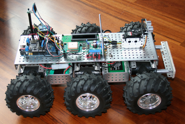
After building a number of indoor robots, we decided to build an outdoor robot capable of traveling through rough terrain. We call it “Trekker.”
TREKKER ROBOT. Six wheels. Six motors. Batteries below deck. Electronics above deck.
First, we put together a six-wheel independent suspension with a separate motor on each wheel and large knobby tires. Each wheel moves up and down separately, which allows this little beast to climb up and over just about any obstacle (rocks, slopes, cats, whatever gets in its way). Here is a video of Trekker going over a large pile of books.
This is by far our funnest robot to drive via Remote Control, but this true magic of Trekker is his navigational capabilities.
We wired Trekker with a GPS chip and a tilt-compensated magnetometer (an electronic compass that works even when the robot is tilted). When Trekker first comes on, he automatically looks for and synchs with as many satellites as he can find in the sky (usually about 10-15). We programmed Trekker to determine his exact latitude and longitude position using the GPS as well as his directional orientation using the magnetometer. He then travels on his own to a series of latitude and longitude waypoints (that we get from Google Earth). Trekker’s navigational algorithm was one of our most ambitious software challenges to date. Our favorite test run is to put him in our backyard and give him instructions to drive around the big tree, down to the barn, drive around the goat pen, and return to us. He does it beautifully, all on his own, moving systematically from one waypoint to another. We also equipped him with a forward-facing sonar, which swivels back and forth on a pan servo, to avoid trees and other large obstacles along the way.

Trekker Robot – Top View – The white square in the middle is the GPS, which is used for navigation. When traveling between waypoints, the Longitude and Latitude display on the little LCD screen.

Trekker – Front View – This provides a nice view of the sonar at the front of the robot, which is used for obstacle detection and avoidance when traveling in automated mode. The magnetometer (compass) is mounted on a tall shaft at the back of the robot to keep it clear of interference from the other electronics, especially the radio.

This picture of Trekker’s underside shows how each wheel connects to a separate motor (black t-shaped things). Each motor housing is on springs and swivels so that it moves separately from the other motors.

Thanks to the shock-absorbing independent suspension of each of its six wheels, Trekker rolls over pretty much anything
Software Modes
We programmed Trekker with a several different modes he can operate in:
- Navigate autonomously to a series of user-provided Longitude/Latitude Waypoints
- Roam autonomously using swiveling front sensor to avoid obstacles and find best path
- Radio Control (RC) – display commands and motor speeds on LCD
- Radio Control (RC) – display longitude, latitude, and heading on LCD
Technical Specifics
- Microcontroller: Arduino Mega
- IO Shield: DFRobot
- Motor Controller: Pololu Trex
- Radio Control Software: Beatty Robotics
- Automated Navigation Software: Beatty Robotics
- GPS: Parallax
- Sonar: Ping
- Sensor Servo: Hitec
- Chassis Parts: Dagu
- Magnetometer: Devantech
- Radio: Xbee
- Batteries: NiMH (electronics) + LIPO (motors)
by Camille | Robots, Slider, Workshop Blog
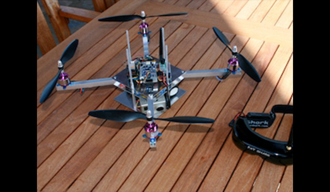
We would like to introduce our flying drone robot. We can fly this robot using Remote Control or it can fly itself using sonar, an on-board GPS, and following longitude/latitude waypoints. We have experimented with various frame designs and electronics, so you’ll see some variation in the pictures. Be sure to check out the video of of me piloting the flying robot.
How We Came To Build a Flying Robot Drone
One day, we asked ourselves, “What kind of robot would you like to build next?”
We both answered, “I want to build a robot that flies!”
We knew it was going to be really hard, but we decided to give it a try. We set out to learn what it was going to take to build a robot that flies. We researched our options, purchased the various motors, propellers, and electronic components we thought we needed, and started soldering. As our initial design came together, we began cutting, drilling, and assembling the various aluminum pieces for the frame, which we knew would have to be both light and strong.
The Features and Design
We decided on a quad rotor design, which is a helicopter-like-thing with four propellers. The left and right motors use normal “puller” propellers and turn counter-clockwise. The front and back motors use “pusher” propellers and turn clockwise. This helps counter-act the torsional forces associated with rotor craft.
The core of the robot’s electronics is a special Arduino microcontroller board specifically designed for auto-piloting drones. This is combined with a special Inertial Measurement Unit (IMU) sensor shield that provides a 3-axis gyro, 3-axis accelerometer, barometric pressure, and other various other avionics sensors so that the robot can sense its tilt, pitch, and yaw in three-dimensional space at all times. The software reads the robots orientation and feeds voltage to each of the motors in proportion to the power that is needed to keep the robot level at all times. This way, the pilot focuses on the direction and speed he wants to go, rather than spending all his time struggling to keep the robot from flipping, spinning, or rolling.
Once we flew and crashed our first design, we made some improvements and tried again. Then we crashed again, made some more improvements, and so on. None of our robots have required more trial and error than this one. But step by step, improvement after improvement, our robot got better and better. Today, it flies very well, has many neat features, and thanks to repeated practice, is relatively crash resistant.
We usually fly the robot using an RC Transmitter. However, it also has many autopilot drone features that we enjoy experimenting with. For example, the robot has an automatic take-off and landing sequence. The robot also includes a downward-facing sonar so that the robot knows its exact altitude at all times. By flipping a switch on our transmitter, we can put the robot in “hold altitude” mode, which tells the robot to automatically and constantly adjust the motors to remain at a constant distance from the ground as we fly it around.The robot is also equipped with a GPS chip so that it knows its exact longitude and latitude at all times. The robot can also follow a series of waypoints uploaded to the microcontroller from Google Earth. It turns out that we were not the only ones trying to build a robot that flies. We have joined with a whole community of people on the Internet (DIY Drones) who enjoy building and flying their own robot drones.
The Mini Flying Drone
We have also built a Mini Flying Drone. Click here to see details.

Mini Quadrotor Drone Robot
The upgraded Black Hornet mini drone
The Future
Although our drones are flying quite well, there is still plenty more we want to do. We look forward to lots of fun and experimentation. We’ve spent most our time building, flying, and improving the robot’s frame and capabilities, but in the future we hope to do more with First Person View (FPV) flying using our video goggles, high-definition arial photography, automatic navigation, and more.
Click here to see our latest flying robot drone, which we made out of carbon fiber.
Flying Drone Robot – Technical Specifics
- Aluminum Frame: Beatty Robotics
- Aluminum, Hardware, and other materials: McMaster-Carr
- Microcontroller: ArduPilot Mega (i.e. Arduino Mega Autopilot board)
- Avionics sensor board: ArduPilot Mega IMU Shield
- Electronic Speed Controllers: (4) m2mPower
- Motors:(4) jDrones
- Propellers: (4) EPP 10×45
- Radio Control Transmitter and Receiver: Futaba
- Battery: 12v 3-cell 20C LIPO
- Magnetomer: DIY Drones
- GPS: MediaTek
- High Definition Camera: GoPro
- VideoTransmitter: ImmersionRC
- FPV Video Goggles: FatShark
Special thanks to the Do-It-Yourself Drones community, especially Chris Anderson, Jani Hirvinen, and the other guys involved with DIY Drones. You guys helped us make our dream of a flying robot a reality. Fly on!
