Aluminalis Crankshaft
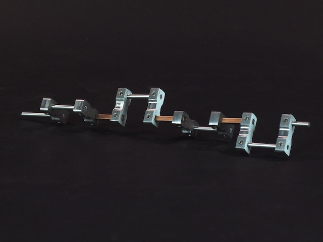
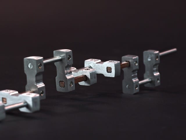
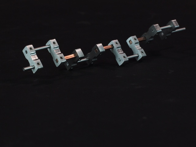
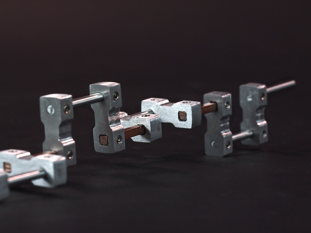
One of the funnest, but most challenging parts of building Aluminalis (our 16-legged walking robot) has been the construction of the two crankshafts. Each side of the robot has a motor that rotates a 10” long, multi-link crankshaft, which drives 4 pairs of legs. The leg pairs need to be kept 90-degrees out of phase from each other in order to produce the walking gait. Our initial vision for the crankshaft was to build it out of 1/8” aluminum round shafts, custom crankshaft arms we made on our CNC, and tiny 4-40 set screws, but when we put it all together for real-life testing, the rotational forces were so high that the set screws couldn’t hold the round shafts, the crankshaft arms slipped out of place, and the entire crankshaft tore apart (not a good day). We went back to the drawing board. We needed a new design. We had the idea of using a square shaft to prevent slippage and guarantee that each of the pairs was 90-degrees out of phase with the others. At first I thought maybe it was a silly, impossible idea. The crankshaft ran through a series of round holes in the body of the robot, so how could a square shaft rotate smoothly in a round hole? Then I realized we could use ball bearings to do that. Our hope was that the square shaft would not only guarantee the 90-degree angle, but it would also give our set screws a flat area to take hold. So, in version two, we used a combination of square shafts, round shafts, larger 6-32 set screws, and bulkier crankshaft arms (that gave the set screws more thread length to take hold). The results were fantastic. The new crankshaft works great in all our real-life tests. Runs strong and smooth. Note that the square shafts are made out of high-strength copper rather than aluminum.