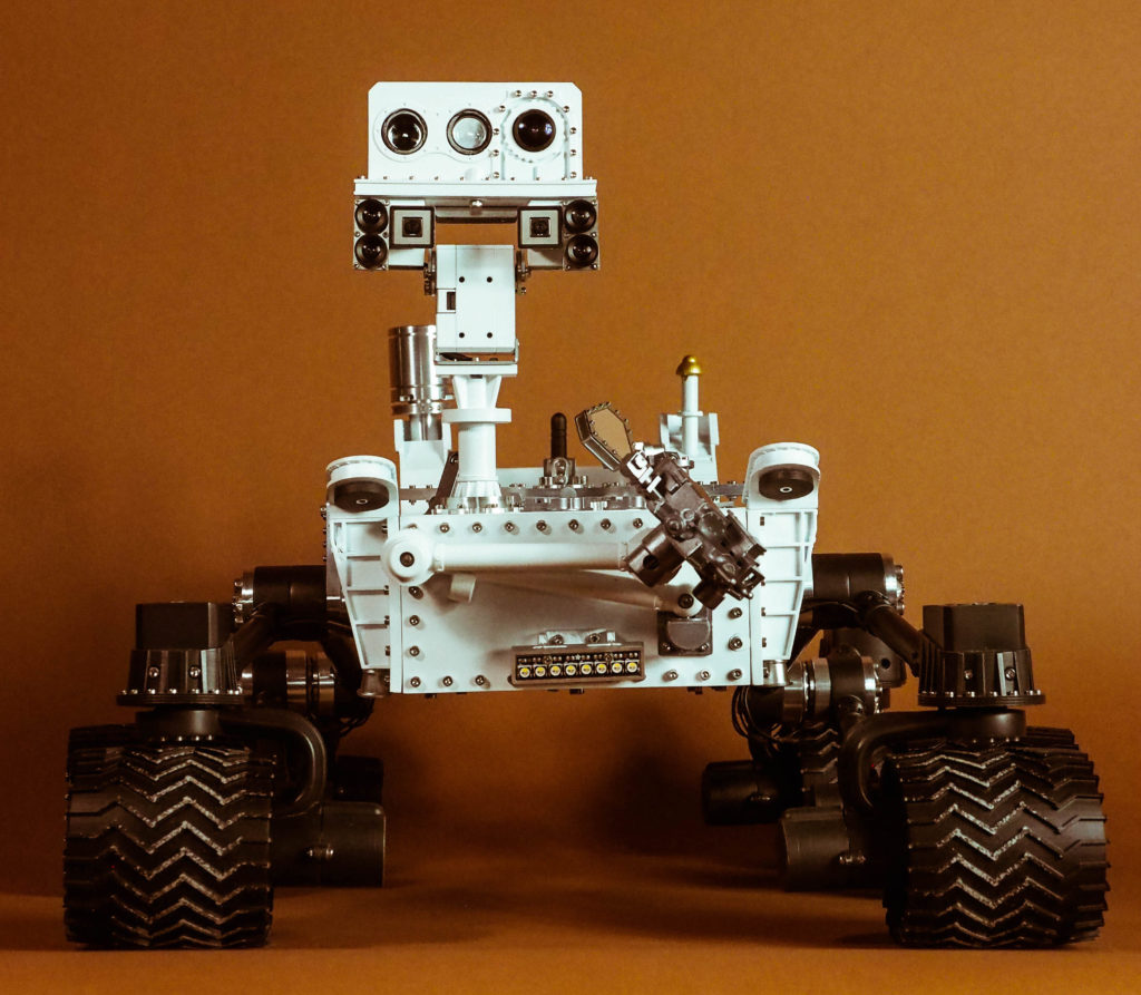
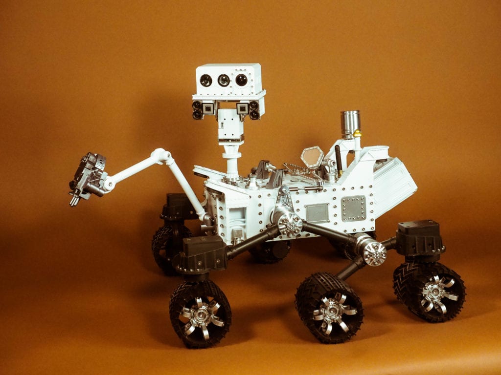
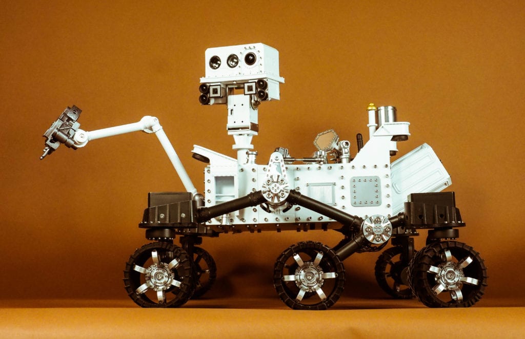
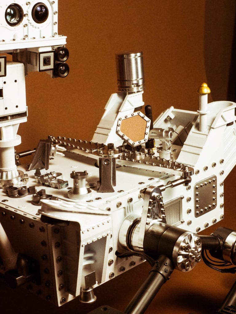
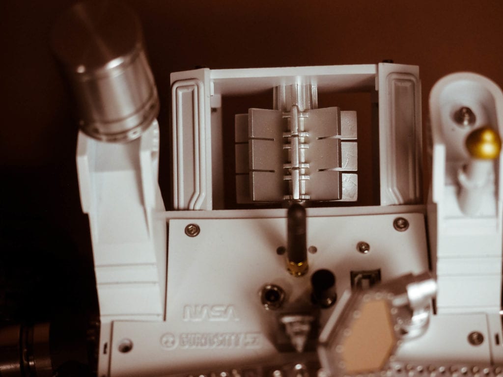
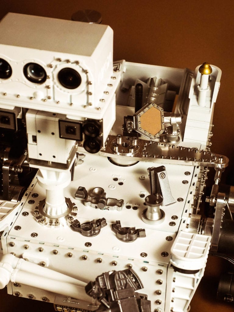
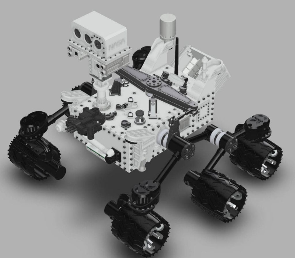
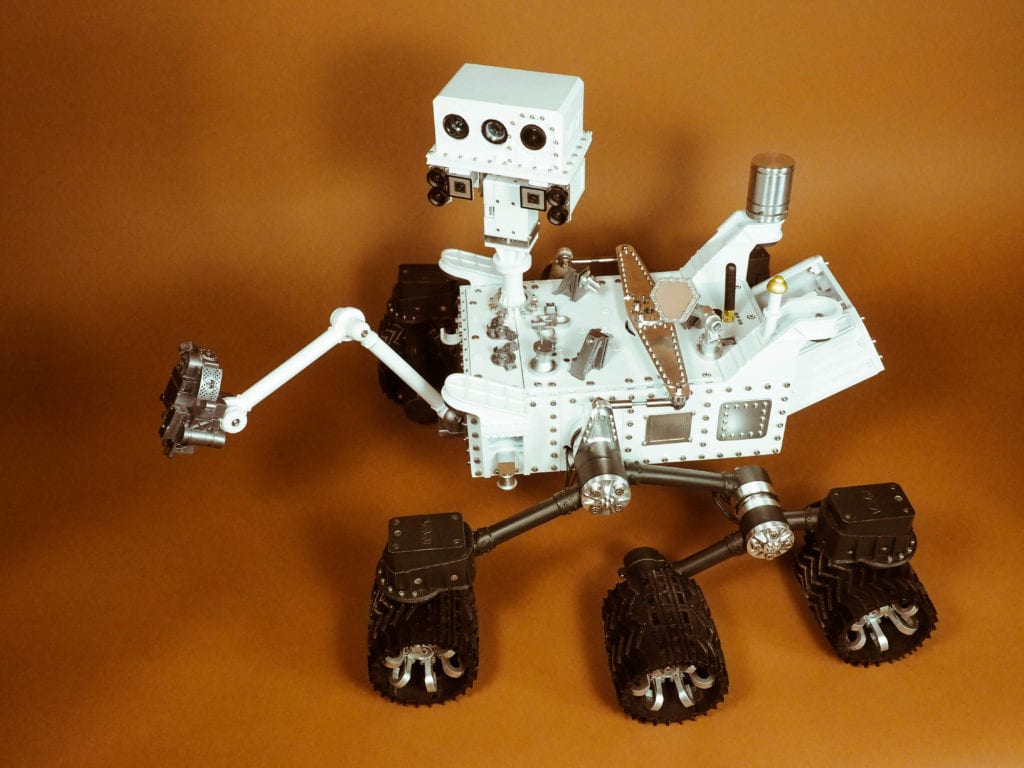
We are excited to share our latest and most ambitious robot, the Curiosity Mars Rover. This is a highly-interactive, 1/10th scale functional replica of the NASA Curiosity Mars Rover. This project was ambitious for us in two main ways: First, we worked very hard to make the robot visually accurate to the original NASA rover. This necessitated custom designing and manufacturing nearly every visible component on the robot. One of the key challenges was to get the required level of detail and functionality into such a small scale robot. Second, we encapsulated all the features and capabilities we wanted for this robot into a robust, maintainable, and modular electronics package based on a stack of custom Printed Circuit Boards (PCB) that we designed. This post focuses on the external view of the robot while future posts will focus on the electronics and functionality.
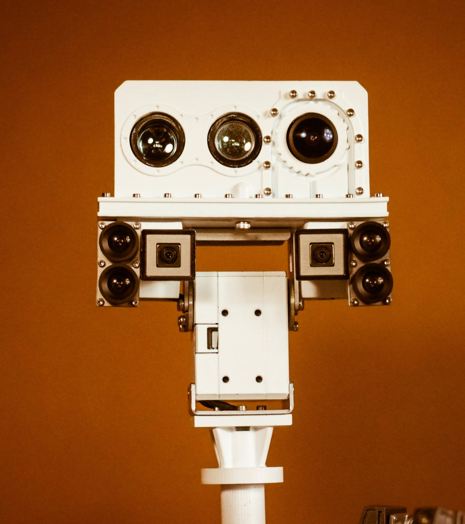
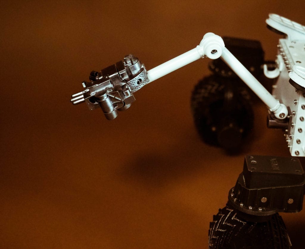
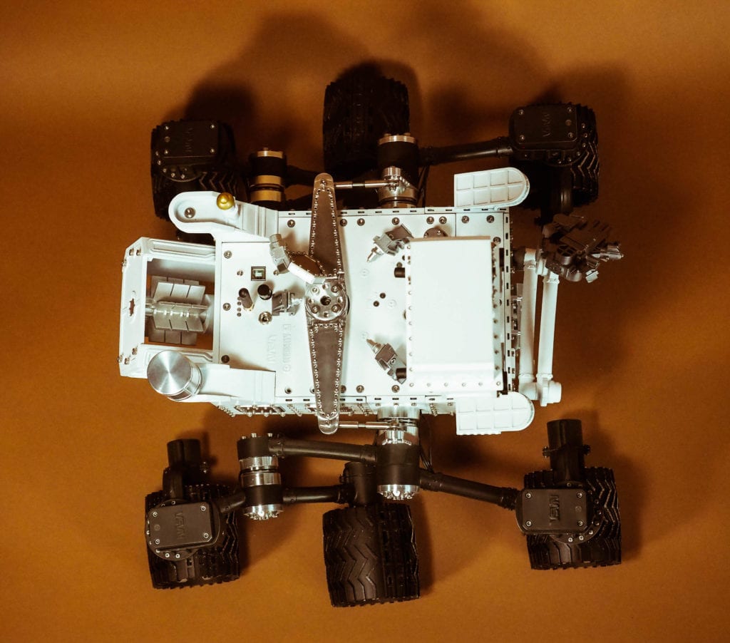
Our Curiosity Mars Rover includes a Six Wheel Drive System (6WD), a fully-functional Rocker-Bogie Suspension System (RBSS), servo steering, a functional differential bar, a 360-degree camera/sensor turret, 3D LIDAR sensing, autonomous behavior, radio data transmission, and much more—all as per the real Curiosity. The rover is approximately 17” long x 20” wide x12” high.
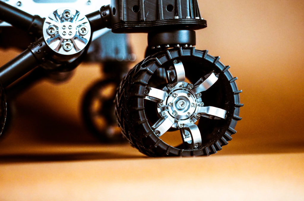
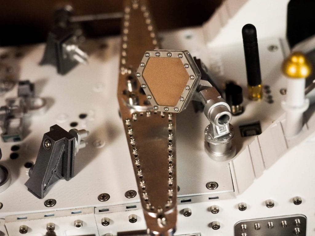
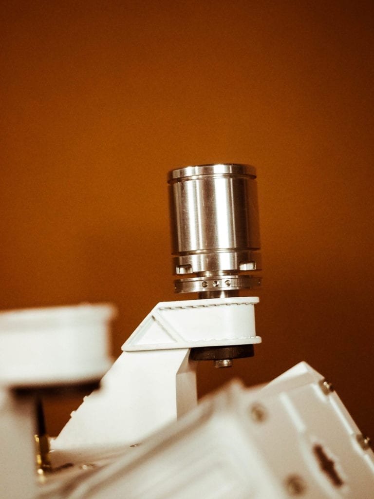
To achieve the visual appearance we wanted, we carefully studied all the NASA photographs and drawings we could find, designed each component using the Fusion 360 CAD software (special thanks to our friend Dan Kreisher!), and then manufactured the custom parts one by one, including all of the body components, chassis struts, wheels, hubs, turret, top deck details, side details, and all the other visible components. All of the white parts, the struts, the servo covers, the wheels, and many other parts were printed in-house on our Formlabs SLA 3D printer out of engineering resin, then carefully sanded and painted (special thanks to Jennifer Beatty and Mike Dutra for helping out in this critical area!). The metal parts were machined out of 6061 Aluminum on our in-house Tormach CNC Mill and/or by our friend John Saunders. Several of the small stainless steel parts (around the camera lenses on the masthead) were laser cut for us by our friends at Pololu.
We’ll provide more details on the electronics and the build in the future, but here is a quick run down of some of our main sources: Pololu: motors, shaft hubs, motor controllers, smart switch, current sensor, and voltage regulators. PCJR: Teensy 3.6 microcontroller. DigiKey: resistors, capacitors, relays, connectors, wires, and all other discrete electronic components. McMaster-Carr: screws, spacers, nuts, raw material, and other fasteners. Robotis: Dynamixel servos. Sparkfun: Xbee radio board, LIDAR, and other electronics. Adafruit: Neopixel and other electronics. Amimon: Connex Prosight HD Video.
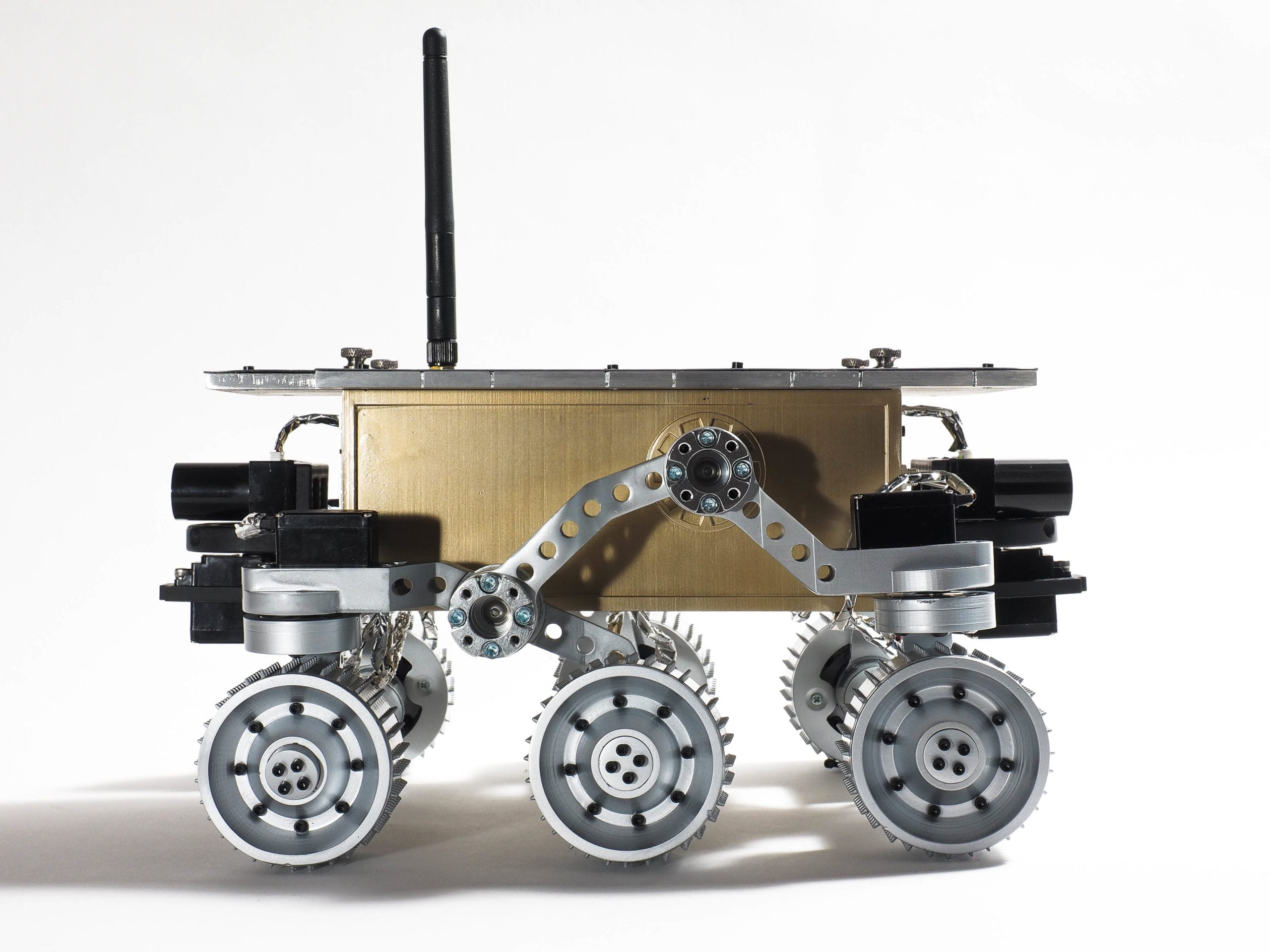
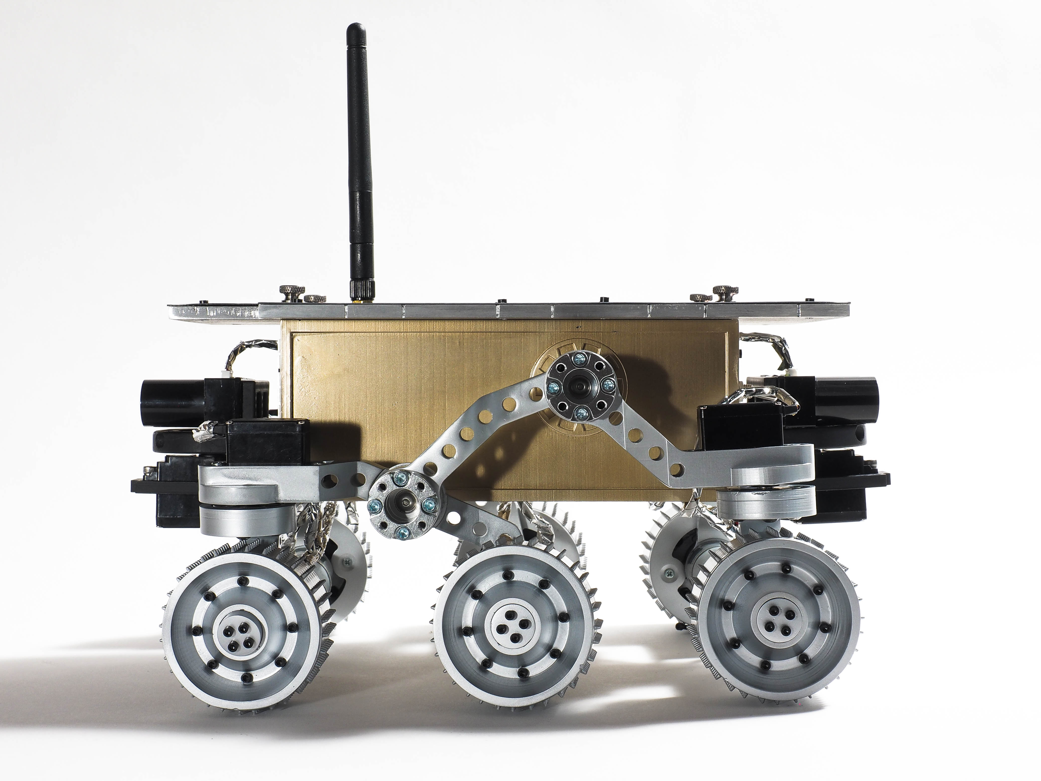
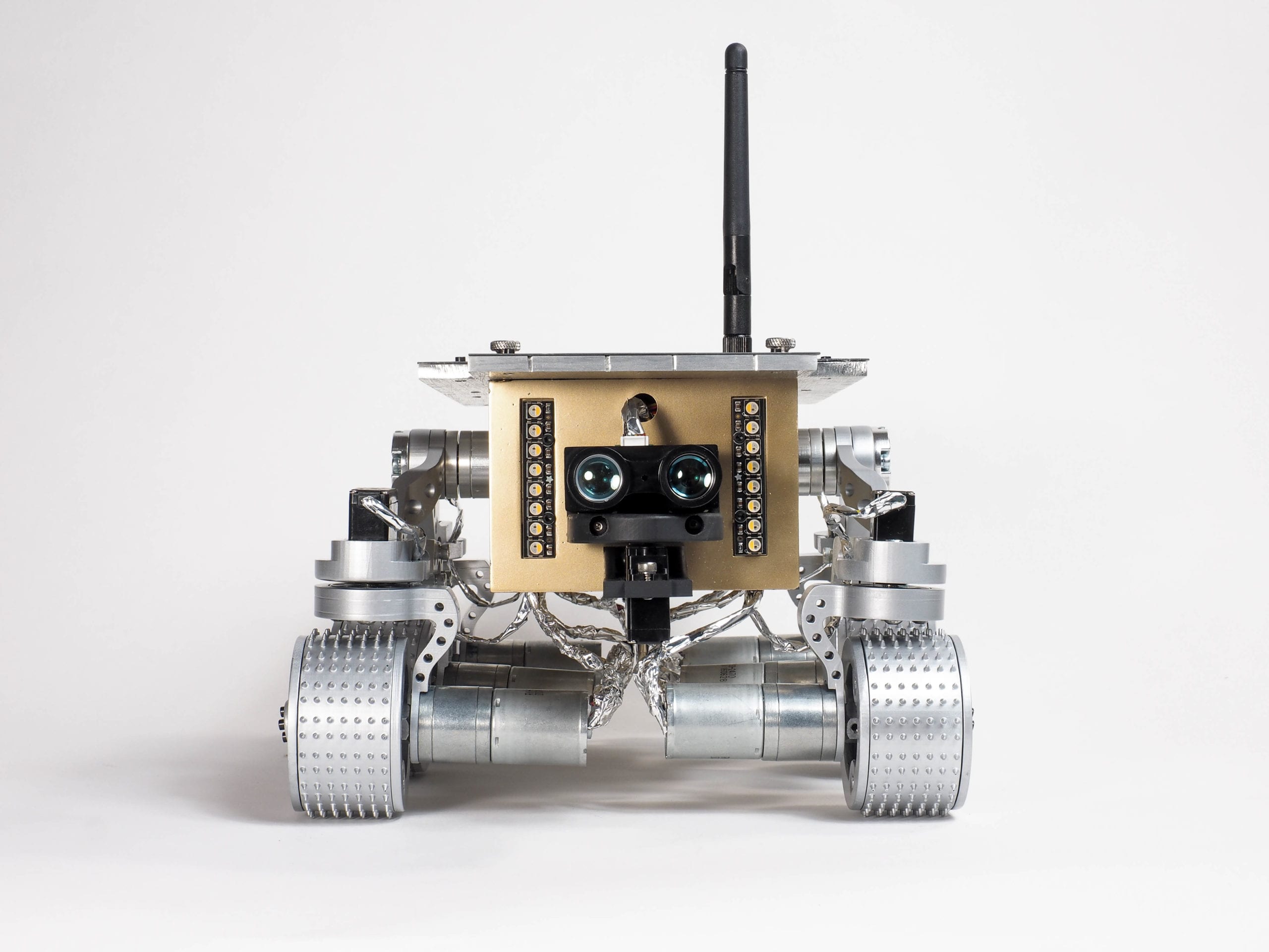
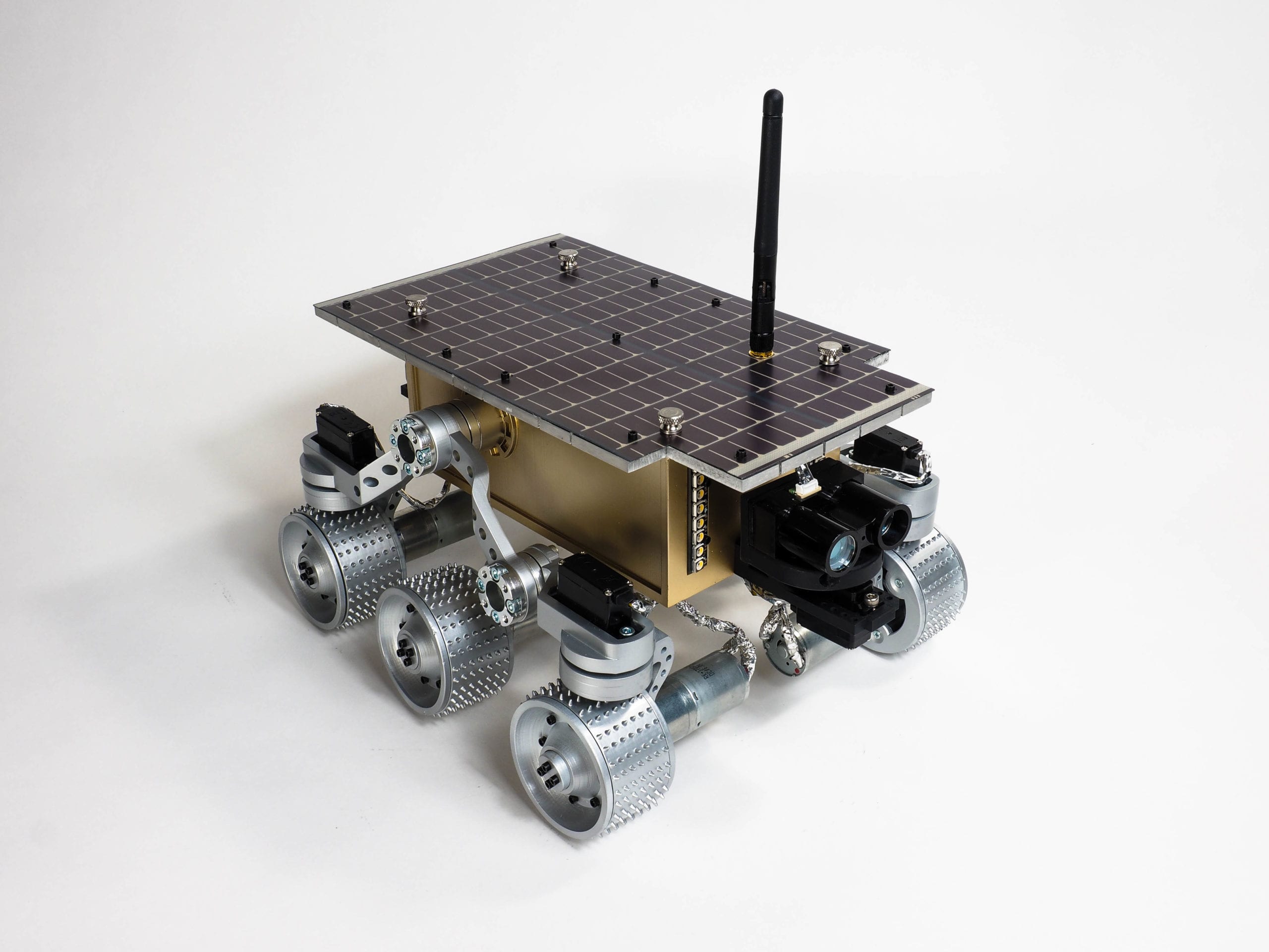
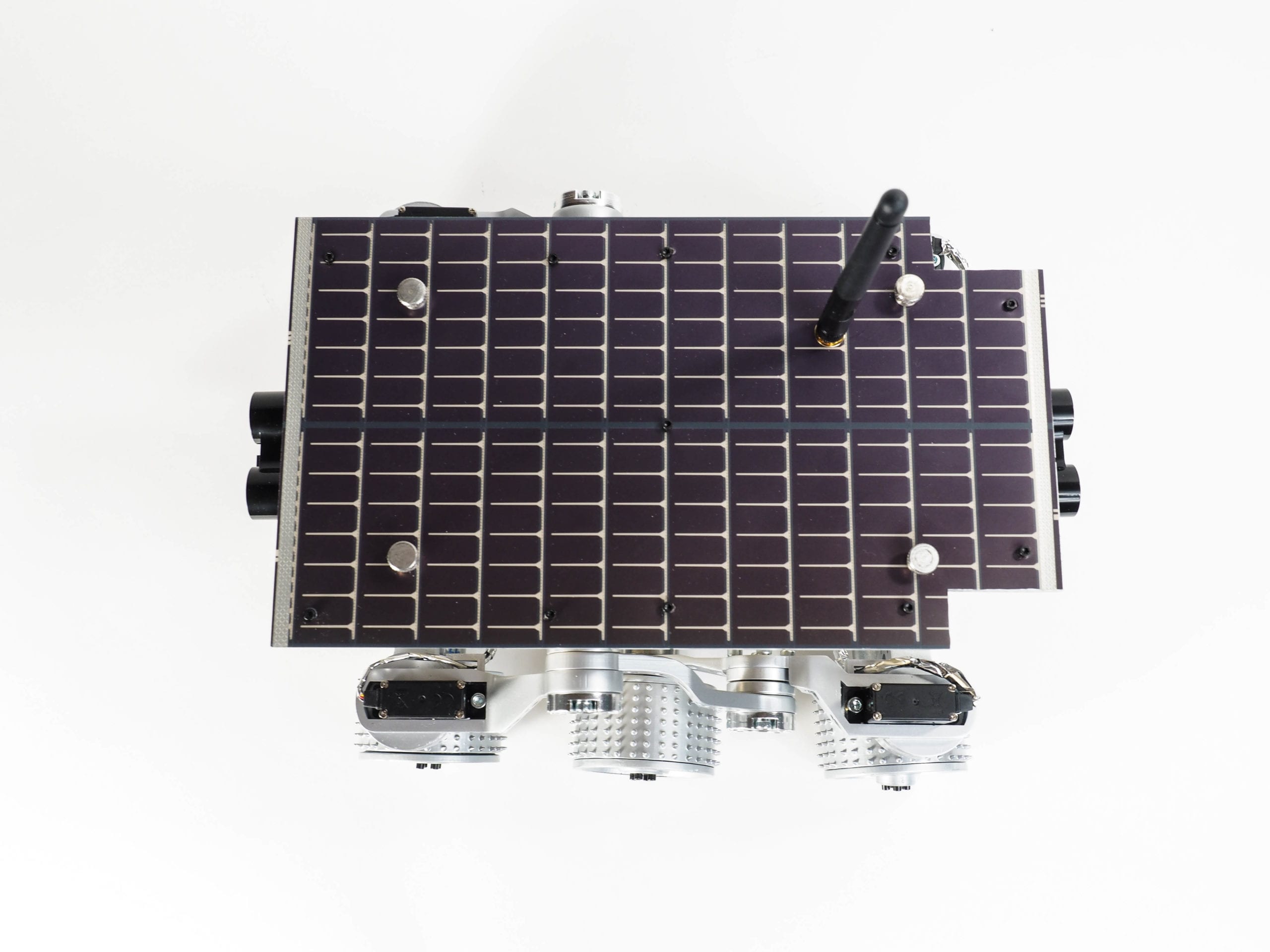
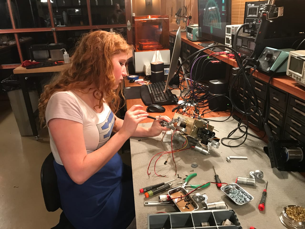
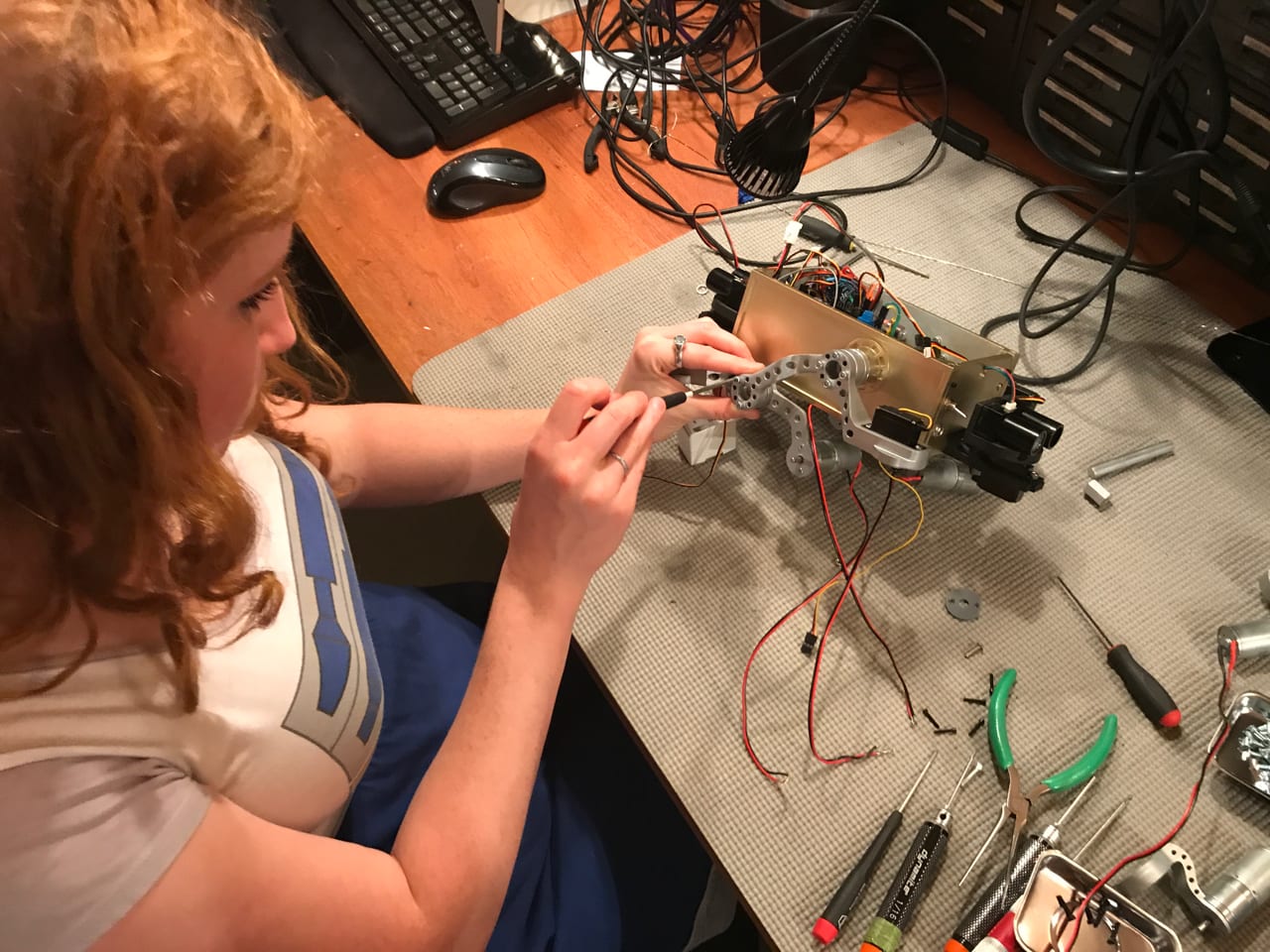
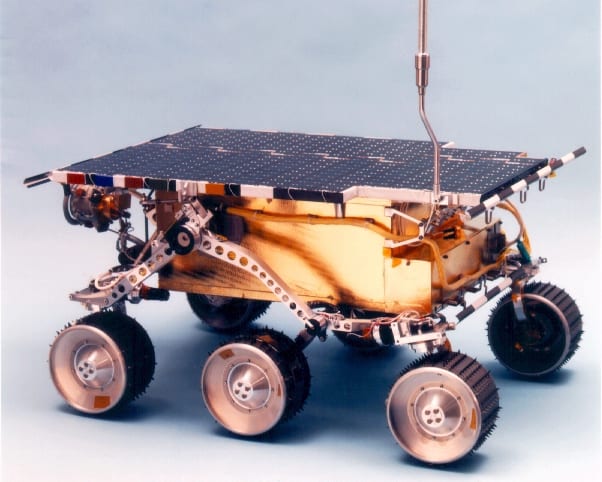
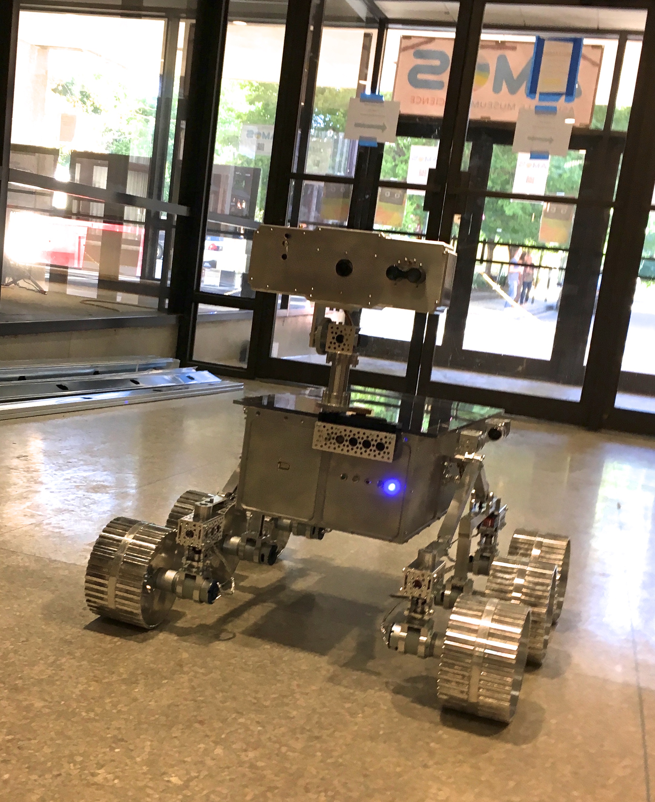
We are super excited to introduce Sojourner, our newest robot. The original 1997 NASA Sojourner was the very first robot to operate on an different planet. Like the real Sojourner, our little robot includes six wheels, rotational servo steering, a fully-functional rocker-bogie suspension system, solar panels, a large main antenna, lithium battery, a “warm box” to protect its electronics, a video camera, and a host of other components. We built our Sojourner in 1/2 scale because it is intended to be used in interactive exhibits in space museums where space is limited. Here are some photos of the robot, followed by work-in-process photos from the workshop, our CAD models, and two images of the real Sojourner for comparison purposes.
We worked hard on the inside of the robot as well. It contains a new thing we’ve put together that we call “The Core”. The Core is a stack of integrated electronics that includes an Arduino Zero, a Servo Shield for controlling the robot’s 8 servos, a custom shield we’ve developed, and a high-powered Motor Controller. We think it’s interesting that the real Sojourner used an 8-bit microcontroller that ran at 2 MHz. Our Sojourner robot uses a 32-bit Cortex M0+ processor running at 48 MHz. In other words, our Sojourner is far more powerful than the real NASA Sojourner. That’s crazy! A lot has happened since 1997!
You may notice that Sojourner is equipped with a servo-mounted laser range finder (LIDAR) on the front and back. As the servo sweeps through 180 degrees, the LIDAR unit shoots out a laser to determine the distance to the nearest object at each degree. This is used for obstacle avoidance and autonomous navigation. Sojourner is also equipped with an HD camera that streams FPV video back to video goggles and/or computer monitor.
Sojourner is equipped with an Xbee radio for transmitting to and receiving from a computer control station. Sojourner is capable of exploring autonomously, or taking a “Command Sequence” (a series of user-programmed movement commands), or real-time manual Remote Control.
This is a small little robot, but it’s become one of our favorites. In future posts, we’ll share some video of Sojourner in operation, a description of the control software, and the details about the new shield we’re working on.
We would like to thank Arduino, Actobotics/ServoCity, Adafruit, Pololu, Ion Motion, and the other companies that provided many of the components. We would like to give special thanks to Dan Kreisher for helping us with the CAD modeling on Fusion 360.
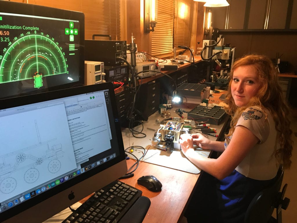
WORK-IN-PROCESS SHOTS
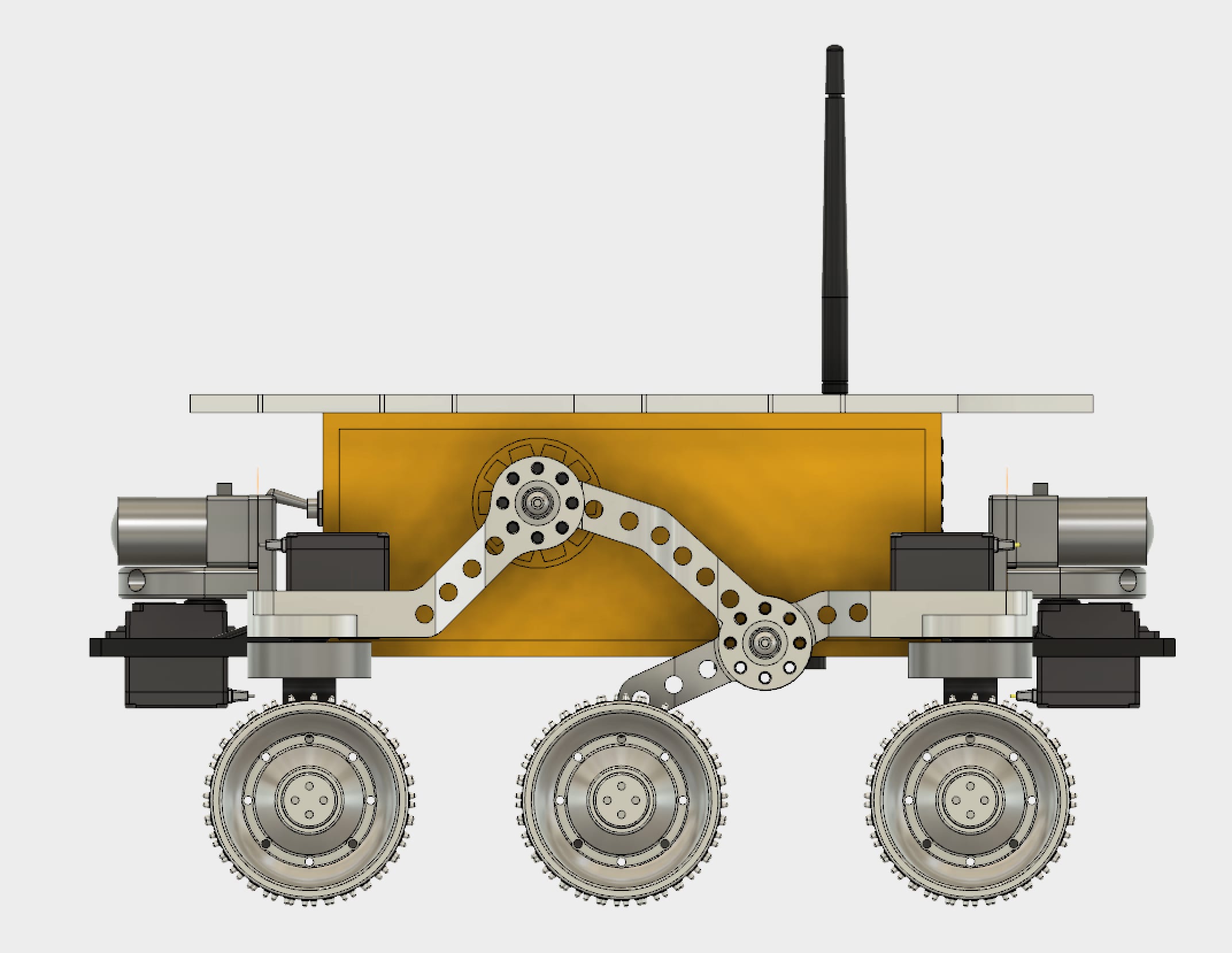
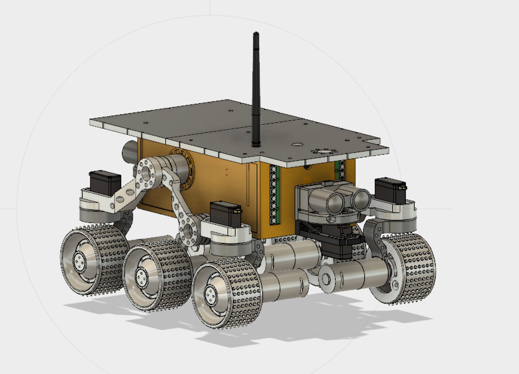
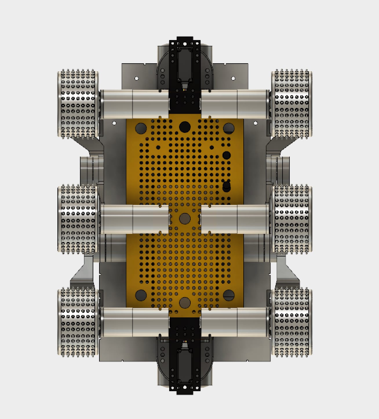
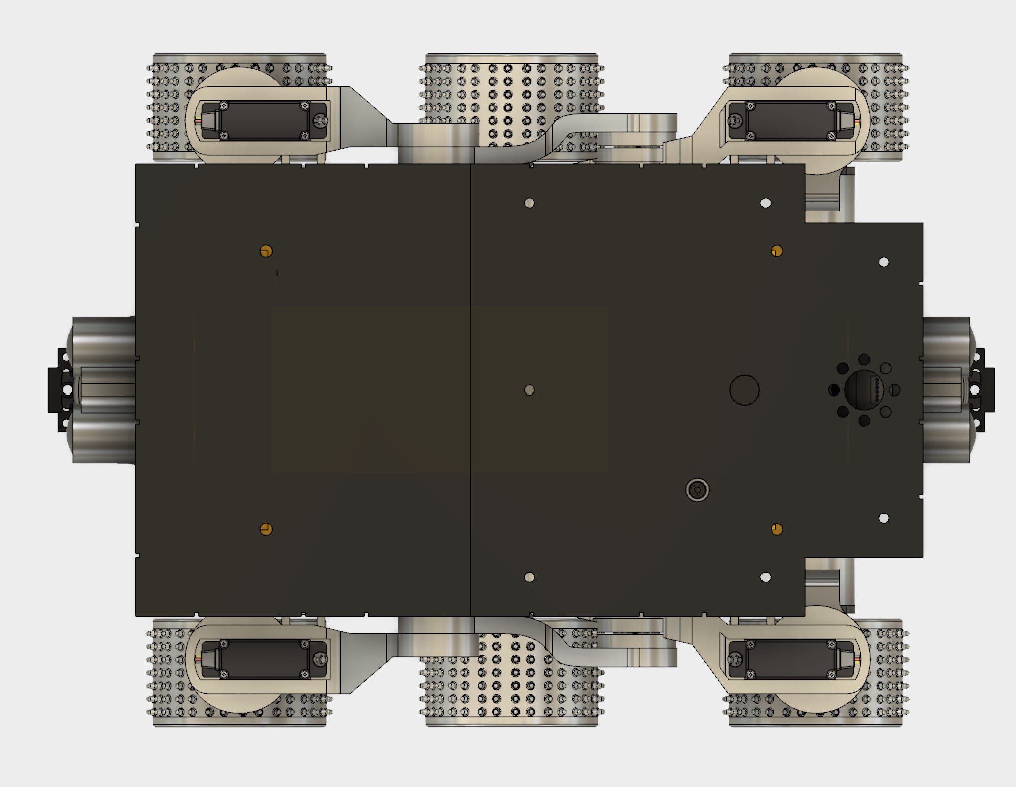
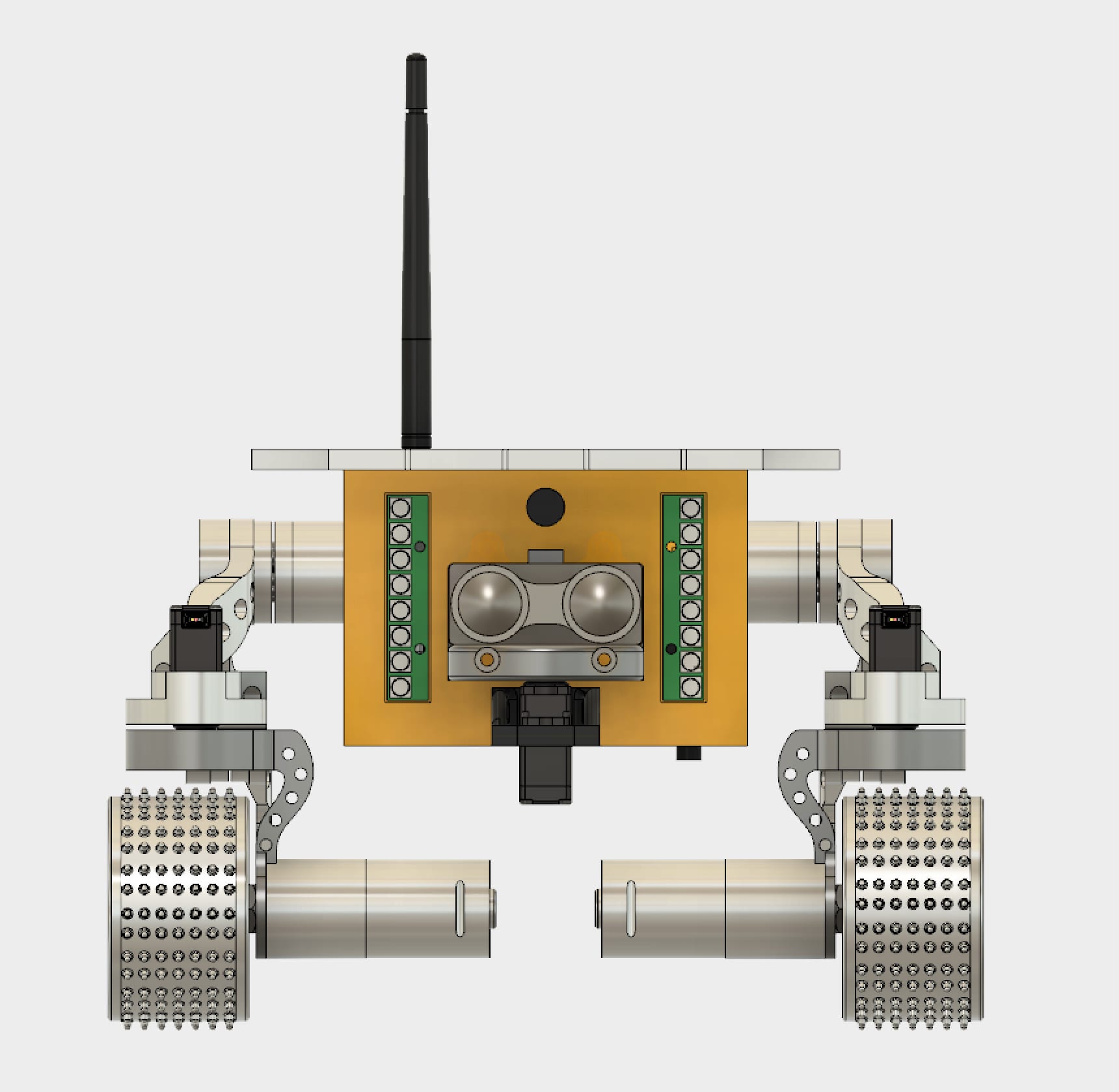
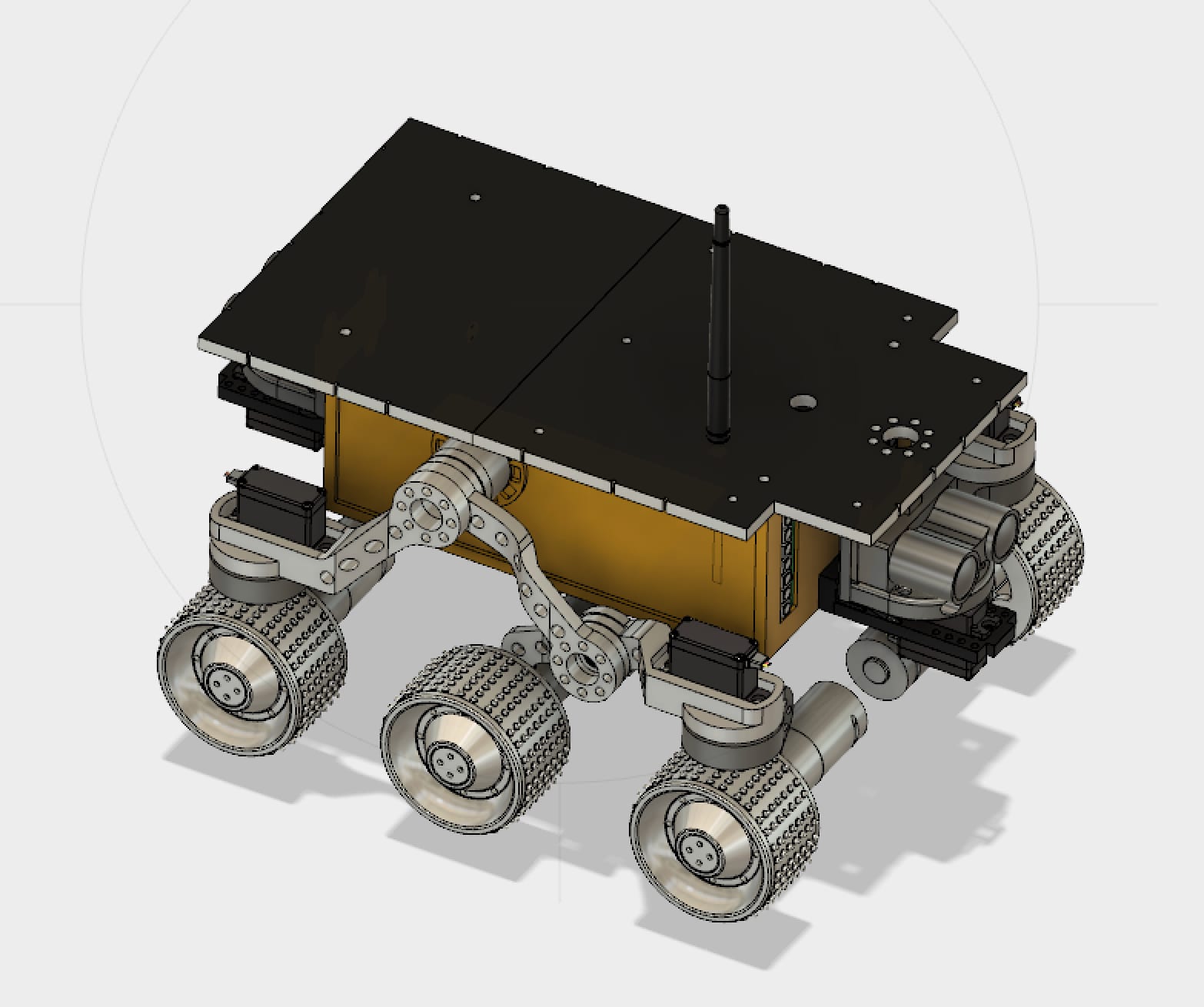
THE BEATTY ROBOTICS 3D CAD MODEL OF SOJOURNER
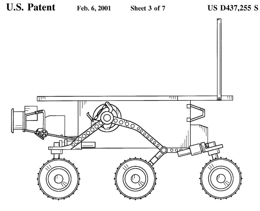
THE FOLLOWING PHOTOS SHOW THE ACTUAL NASA SOJOURNER ROVER
(Please note that the robot’s tread’s look blackish in this photo, but in reality the machined aluminum wheels had sheet-metal teeth, not rubber. Rubber would freeze and shatter on Mars)
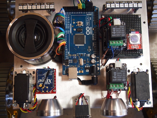
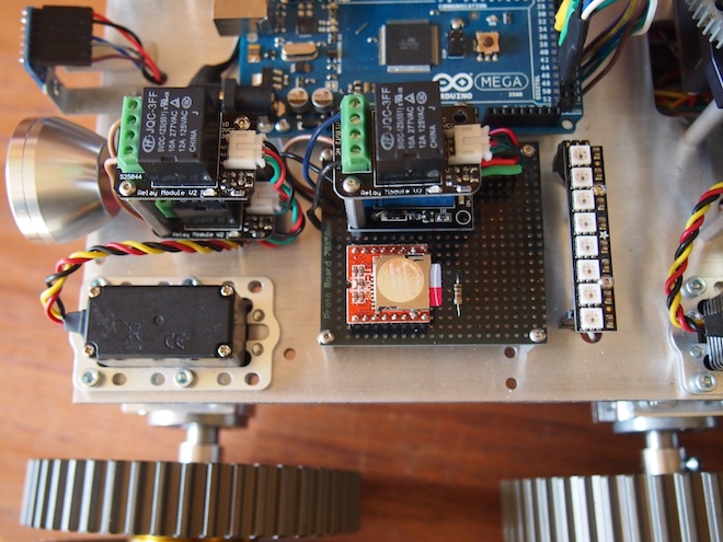
We often add sound effects and even music to our robots. We’ve used a number of approaches, but our latest method is the SOMO-II MP3 Module. Here are some pictures (from a rover robot we’re working on) and the technical details of how we integrated the SOMO module. First, here is a top view showing the speaker on the left, the Arduino in the middle, a stack of relays, and the SOMO (orange and silver colored square) on the right.
A closer view of the SOMO mounted on female headers soldered to a black protoboard. You can see the microSD card sticking out, which will give you an idea of how small the SOMO is. You can also see the 1K Ohm resister, which is required to get it to work.
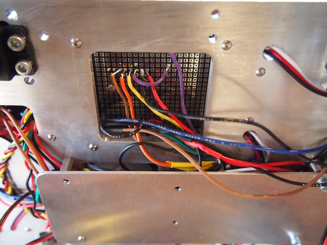
The underside of the prototype board. The SOMO is using the brown, orange, yellow, purple, black, and red wires. The other wires are unrelated.
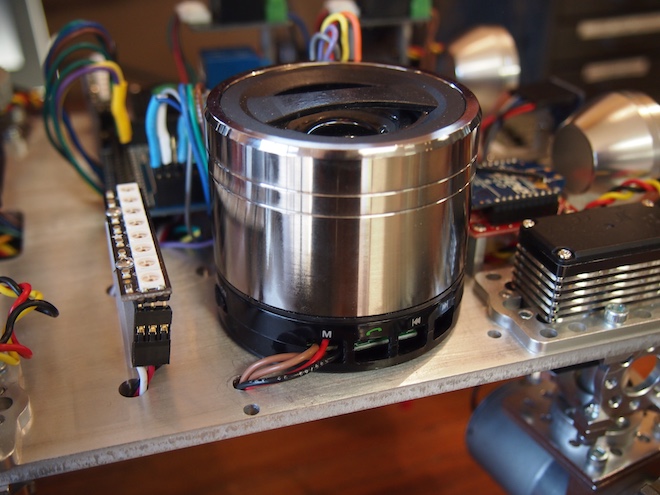
We took a powered USB speaker apart, hacked into it, and screwed it to the main plate. We pulled out the speaker’s battery and wired the speaker into the robot’s main 5V battery. We also rewired the speaker’s buttons so that we could control its functionality using an Arduino-controlled relay to change its mode so that it will receive an incoming external audio signal.
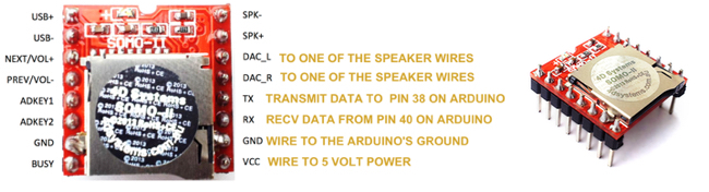
Here are the steps to get the SOMO setup: First, put your mp3 sound files onto a microSD card. The files should be in a folder called “01”. And they should be numbered 001xxxxx.mp3, 002xxxxx.mp3, and so on, where xxxxx is any name you want to give them (or no name at all, just the number prefix). The main thing is that the files need to begin with the numeric sequence as shown. Next, wire the SOMO to your Arduino and a powered speaker like this. We used Arduino pin 38 and 40 on our Arduino Mega, but you can use whichever suitable digital pins you wish to (or Serial1, Serial2, or Serial3 on a Mega).
Important Note: The SOMO operates at 3V. If your Arduino operates at 5V (which most do), then solder a 1K ohm resistor on the SOMO’S RX Line. For the speaker, purchase a small, powered USB speaker and cut open the stereo audio cable. You’ll see three wires: white, yellow, and orange. Solder the white wire to the project’s ground. Solder the other two wires to DAC_L and DAC_R. These provide “line out” for a stereo headphone jack, external powered speaker, or amplifier. If you are using a small, non-powered speaker, then use SPK- and SPK+ instead.
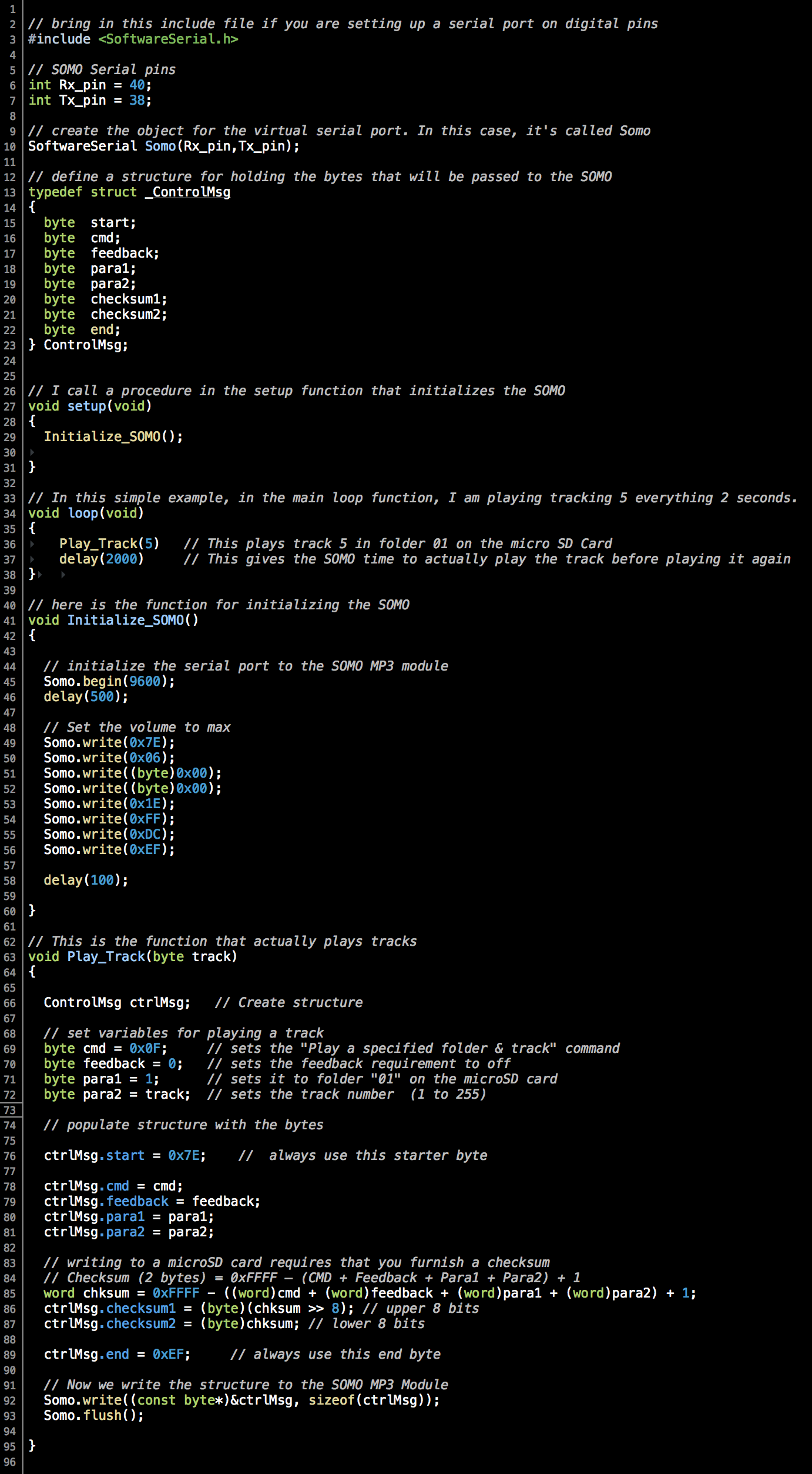
The Arduino source code was the trickiest part. We couldn’t find any libraries or examples of using the SOMO with Arduino, so we wrote our own. Thank you to Curtis Whitley for helping us to figure out how to calculate checksums. At the bottom of this post, we’ve provided a sample program that shows how to play an mp3 track from the microSD card. It provides an example of exactly how to operate the SOMO-II from an Arduino.
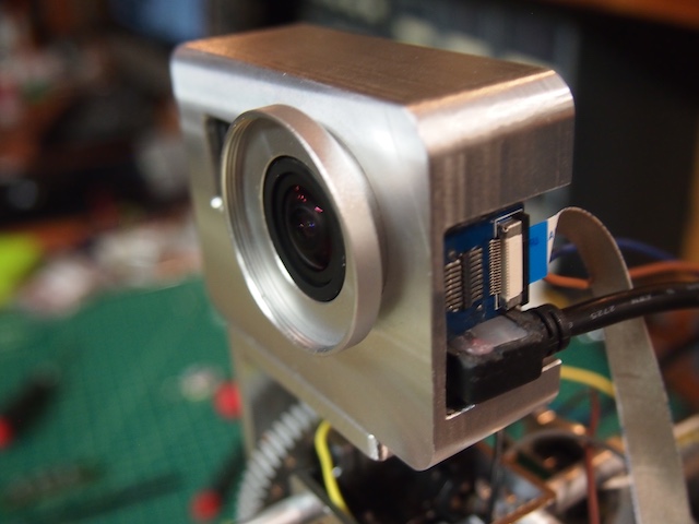
We are in the process of mounting a GoPro camera onto our latest robot. In our previous post we showed how we hacked into the GoPro and wired it up so that we could control it from the robot’s Arduino microcontroller. The next task was to design and machine a case for it. As usual, the CAD design work took longer than the actual machining. It was a fun and challenging little machining project. The end result isn’t perfect, but I think it came out pretty nice, and it will definitely serve the purpose. Our case needed to have these characteristics:
Protect the GoPro and make it look cool on the robot.
Provide slots for running the remote control wires.
Cover up all the GoPro’s buttons so that museum participants and technicians can’t play with the buttons (and mess up the settings in the camera). The camera will be entirely controlled by the robot.
Provide specialized tapped mounting holes for specific placement on the turret of our robot.
Provide a lens cover to protect the GoPro’s lens.
Provide space and protection for the HD transmission cable and modified USB cable plugged into the side ports.
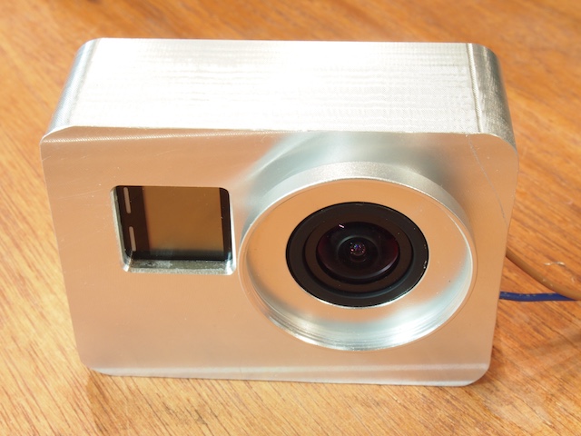
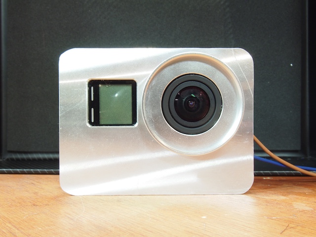
FRONT VIEW OF CAMERA IN CASE
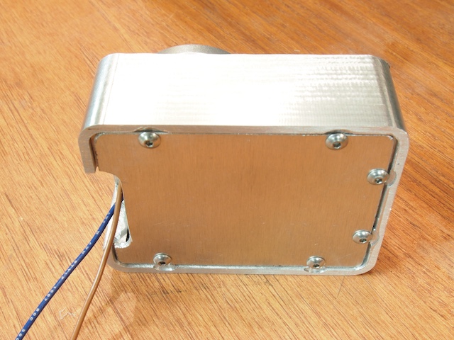
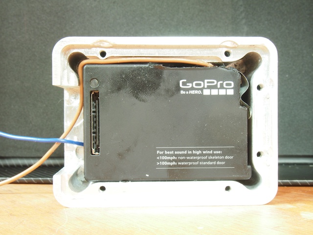
REAR SIDE WITH REMOVABLE PLATE
CORNER VIEW SHOWING HD CABLE AND USB CABLE PLUGGED INTO PORTS
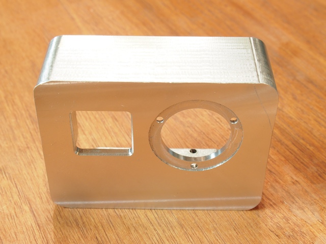
EMPTY CASE BODY MACHINED ON CNC
REAR OF THE CASE BODY SHOWING WIRE SLOTS AND OTHER DETAILS
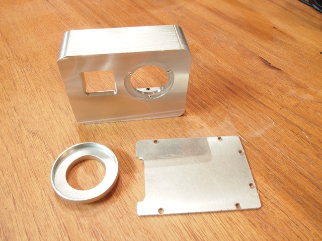
THREE COMPONENTS OF THE CASE (2 custom machined parts + a lens circle hacked from something else)