by Camille | Robots, Workshop Blog
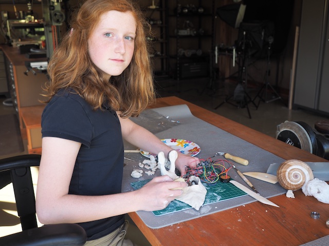
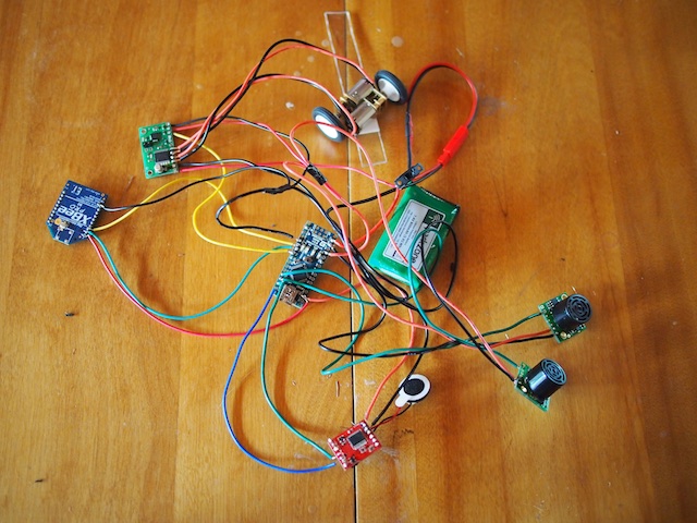
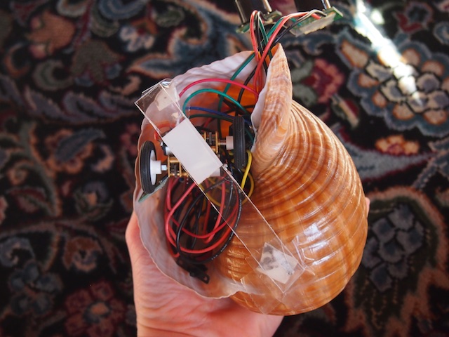
Snailbot is one of my favorite pet projects. 🙂 The idea is to build a robot inspired from a biological creature, in this case, a snail. The first challenge was to design and wire-up the electronics so that they would fit inside the limited space of the snail shell. The electronics include an Arduino Nano microcontroller, a motor controller, two tiny gear motors with wheels, a lithium-polymer battery, an xbee radio for data transmission and remote control, an SD card and sound module, a tiny speaker for sound effects, and two ultrasonic sensors that will serve as Snailbot’s eyes.
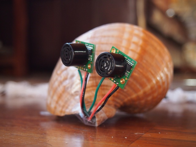
THE EYES OF THE ROBOT STICKING OUT OF THE SHELL PRIOR TO SCULPTING THE EYE STALKS
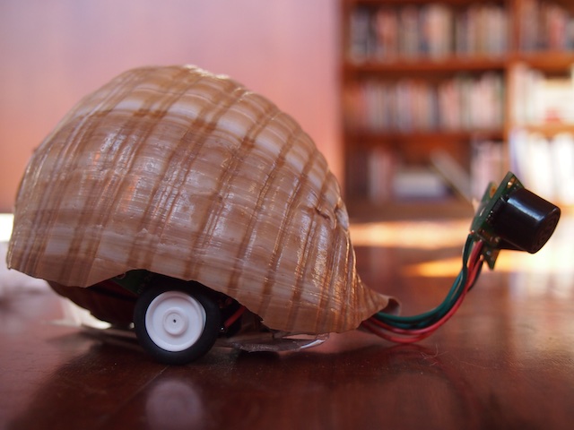
SNAILBOT SIDE VIEW PRIOR TO SCULPTING THE MOLLUSK PORTION OF THE ROBOT
SNAILBOT’S SHELL

THE ELECTRONICS IN THE SHELL
I’M MOLDING WET CLAY TO CREATE THE SOFT MOLLUSK PORTION OF SNAILBOT
SCULPTING THE EYE STALKS

Snailbot isn’t done yet, but I’ve made good progress.
by Camille | Robots, Slider, Workshop Blog
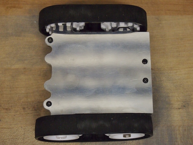
This is Tinybot. About 3″ long and just 1.5″ high, this is one of the smallest robots we’ve ever built. Starting with a Pololu Zumo drivetrain, we set out to see if we could get all the components of the robot INSIDE what was originally its 4 AA battery compartment. We used our CNC to make a cool aluminum top plate. Two tiny gear motors drive the rubber treads. We cut the pins off an xbee radio and soldered it directly to an Arduino Nano’s 3V pin and digital pins so that we didn’t need to waste space with an adapter board or wires. The robot also includes a tiny motor controller, a little 800 mAh 7.4V LIPO battery, and a rocker switch. This neat little robot works beautifully. It zips around with incredible agility, either via xbee-based remote control or through a pre-programmed autonomous pattern. It can drive forward, backward, turn, rotate, and even drive upside down. We built this robot quite a while ago and are just getting around to posting it now, but it was this little guy that gave us the confidence to know that we could build small intricate robots like Lunokhod and Mini Mars Rover.
Top view of our Tinybot with our custom CNC-machined aluminum top plate.
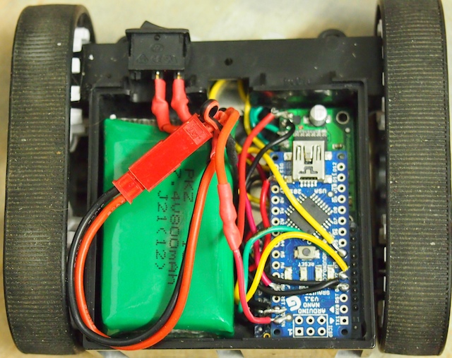
The Tinybot with the aluminum plate removed. The green thing on the left is the tiny LIPO battery. The blue thing is an Arduino Nano without headers. The motor controller circuit board and the hacked down Xbee module are laying flat below that, stacked in layers.
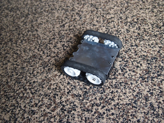
Tinybot

by Camille | Non-Robot Projects, Tools and Workshop, Workshop Blog
Today, we worked on the wireless telegraph project. We decided to mount the electronics on brass and copper plates, so we designed the parts on the CAD system and then machined the parts on our home made CNC mill (one of our many projects over the last year). Using the CNC to make project parts was a really cool use of what has become our favorite tool. Here are some pics of the CNC.


Here is our CNC mill just after machining the copper telegraph base plate. Top left: the computer and electronics box we built. Top center: Cooling tower for the water-cooled spindle. Top right: The 3-phase Variable Frequency Drive (VFD), which powers the 24,000 rpm spindle, is mounted on the wall. Mounted on the wall just below the computer box: an LCD panel for the CNC user interface. Right hand side: The stepper-motor-driven CNC machinery, which is made out of steel and aluminum. You can see the copper part on the blue riser (which is machinable wax). Front center: the system’s keyboard, the emergency stop button box we built, and the jog box (for moving the CNC manually).

A close up of the copper base plate just after it has been machine by the CNC.
Camille showing off her new copper base plate, fresh out of the CNC

We needed two of the base plates (one for each side of the telegraph system), so we machined the second one out of brass instead of copper (using the same CNC file).

Here Camille assembles the telegraph electronics onto the baseplate

Here are the electronics for the telegraph system mounted on the copper plate. The electronics shown here include an Arduino Nano in a screw terminal board, a 7.4v Lithium Polymer Battery, an Xbee Radio, a potentiometer (for tuning the voltage to the Telegraph Sounder), and a small speaker). This copper plate will be mounted inside the base of the telegraph system.

by Camille | Non-Robot Projects, Workshop Blog
Here at Beatty Robotics, we have a keen interest in mixing cool, old technology with exciting new technology. Recently, we became interested in Morse Code and telegraph equipment. We began exchanging written secret messages in Morse Code. And then we continued on by learning to tap the codes with rocks and listen to them at some distance. We are still learning and practicing, but it’s pretty clear that they are getting better and better and will soon be fluent. So now we’ve embarked on our next project, which is to build a functioning telegraph system by refurbishing several very old, antique telegraph keys and sounders, and then combining then with our modern electronics knowledge. We aren’t ready to show the completed project quite yet, but here are some pics of us wiring up the electronics. As we complete the project over the next few weeks, we’ll post pictures of the complete telegraph system (we’re hoping it’s going to look pretty cool), an explanation of how it all works, and the list of components.
Genevieve solders the headers on the Arduino Nano while I wire up the screw terminal board

I power up our wireless Xbee LCD screen to see if test messages are being transmitted properly from the Telegraph key. (The telegraph system itself won’t include an LCD screen. This was just for a test.)

Working together on some delicate soldering on the main microcontroller
See the finished product here: Wireless Telegraph
by Camille | Robots, Slider, Workshop Blog
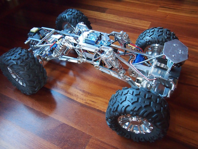
Today, we would like to introduce Terrabot, our Terrain Traveling Robot. Based on a modified “rock crawler” chassis, its primary purpose is to traverse rocks, branches, steep slopes, flower beds, boulders, mountain trails, and other extremely rough terrain.
Terrabot

Terrabot is equipped with 4-wheel steering (4WS). Two high torque servos shift machined aluminum linkages to rotate its front and back wheels independently. Note the navigation GPS on top of the back servo (on the left) and the sensor turret on the front (right). Terrabot’s four wheels are driven by two powerful brushless motors (bright blue) and robust gearboxes (centered in each axle).

Terrabot’s highly-articulated chassis is designed to twist up to 90 degrees as the robot is moving, allowing it to climb over huge boulders and other obstacles. In this picture, the chassis is articulated 45 degrees. Note that the back tires are still on the ground because the center linkages of the bot are twisted.

Terrabot’s topside electronics include a tiny Arduino Nano (lower left), an XBee Radio (right), and a 9-DOF Mongoose Inerntial Measurement Unit (IMU). The IMU measures the degree of tilt and the rate of acceleration in the X, Y, Z planes, which we plan to use for our stabilization algorithm.

Terrabot’s other electronics are stuffed into the little chamber inside the aluminum core (note the blue LED at the bottom of the picture). This includes the two Electronic Speed Controllers for the motors, the Pololu Maeastro motor/servo controller, the power rails, various voltage regulators, and other electronics. The navigation GPS (see the first picture), is mounted on top of the rear servo so that it has a clear view of the sky.

Terrabot Side View, showing the shocks, the frame, and LIPO battery beneath. Note the “roll posts” we installed on the top to protect the topside electronics if Terrabot falls off a rock during a climb and flips over. (We learned this one from experience!)

Terrabot Front View. There are three sonars mounted in the sensor turret, which rotates 270 degrees when the robot “looks around” to determine the best course through obstacle-ridden rough terrain.
