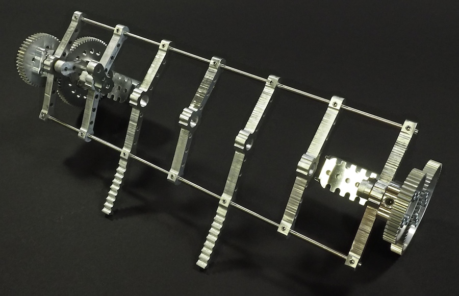
We had good success with our 16-legged walking creature Aluminalis, so we decided to use what we learned and build a new walking creature. We plan for this to be a much smaller, faster, and more agile little beastie. We call her Alumini (Ah-lu-min-ee). Instead of 22″ wide, she’ll be just 10″ wide. Instead of using bulky rectangular segments, we’ve designed much finer segments, like bones in a spine, with built-in pockets for ball bearings to hold the all-important crankshafts. We’ve also designed a custom motor-and-gear mount for each end that holds everything together. Alumini will have twelve legs instead of sixteen. And instead of having a large visible thorax (body), all the electronics will be integrated within and beneath the legs of the robot, so she’ll appear to be nothing but legs. Here are some pictures of our work-in-progress. The crankshaft and legs are not shown. We’re just working on the skeleton and overall structure at this point.
PARTIALLY-CONSTRUCTED SKELETON
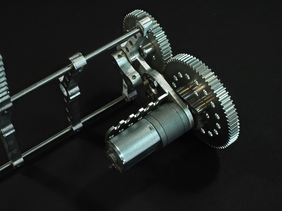
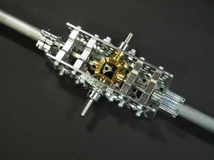
MOTOR AND GEARS MOUNTED ON CUSTOM END PIECE
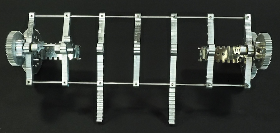
SKELETON TOP VIEW
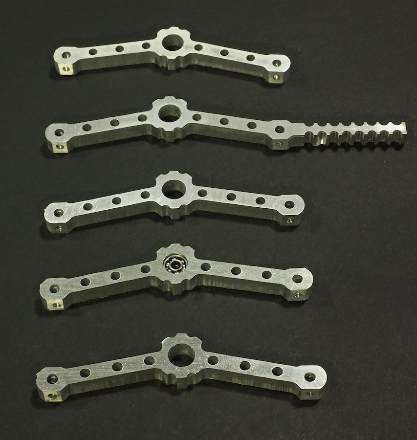
BONE-LIKE SPINE SEGMENTS MACHINED ON CNC
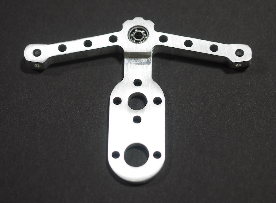
SPINE SEGMENT WITH BALL BEARINGS (TO HOLD CRANKSHAFT) INSTALLED IN SPINE
CLOSE-UP OF MOTOR-AND-GEAR MOUNT
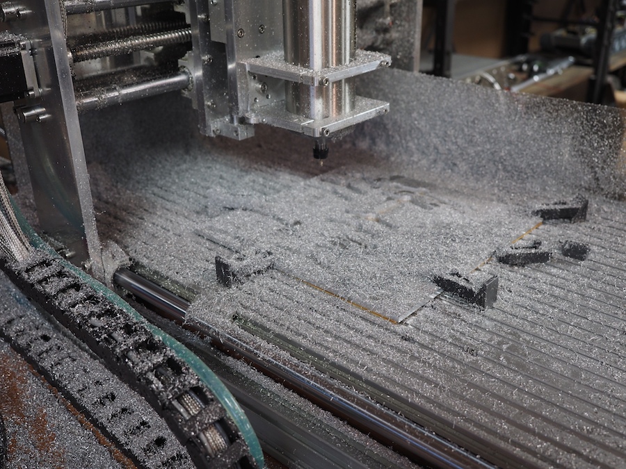
CNC COVERED IN CHIPS AFTER MACHINING THE PARTS FROM A 12″ x 12″ SHEET OF 1/4″ THICK 6061 ALUMINUM
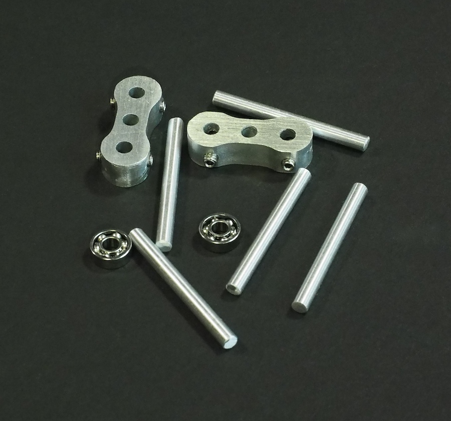
CNC-MACHINED CRANKSHAFT ARMS ALONG WITH BALL BEARINGS AND SHAFTS
Back in November of 2011 we posted an article about our first Spirit II Mars Rover. Among other things, that rover included a counter-rotating differential (or universal joint) integrated into its rocker-bogie suspension system. If the front wheel on the left side of the rover went upward over a large obstacle, then the differential would push the three wheels on the right side downward, and vice versa. Its purpose was to stabilize the rover when traversing rough terrain. We made that first counter-rotating differential from bevel gears, aluminum rods, aluminum plates, and screws. Its shafts were connected to each side of the rocker-bogie suspension system. The function was simple: If either of the shafts rotated, then it caused the other shaft to rotate in the opposite direction. Our original version worked quite well, but it was also large, bulky, and a bit difficult to keep running smoothly.
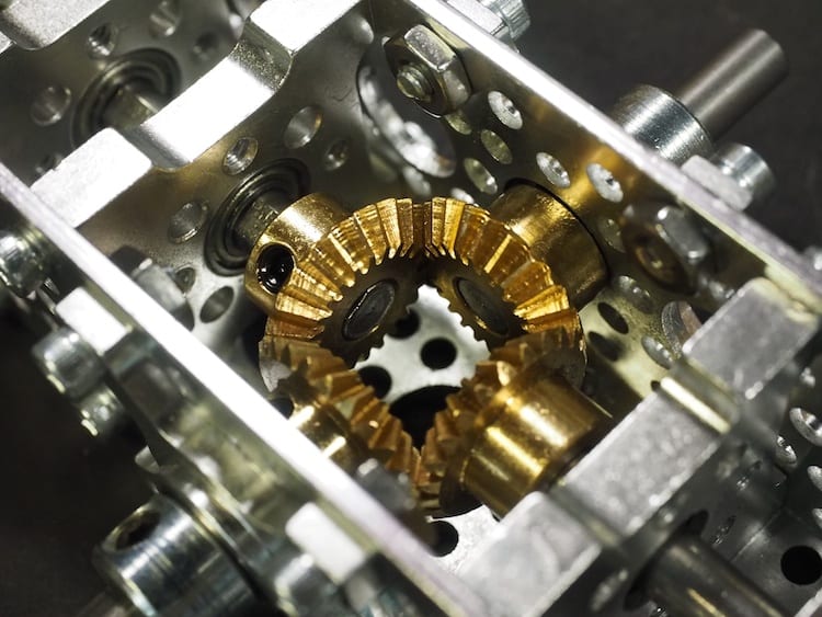
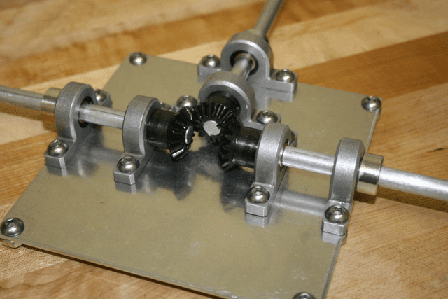
Recently, our friends at Actobotics / ServoCity sent us a couple of their new bevel gears to try out. It’s cool how a few new parts can fire up your imagination and get you thinking. We decided to see if we could create a new counter-rotating differential for a future Mars Rover project. We were very pleased with the results. The new differential is much smaller than the old version, so it will fit nicely inside the box of a Mars Rover, and its operation is smooth and robust. Camille took all the photos of the new differential.
THE NEW COUNTER-ROTATING DIFFERENTIAL
CLOSE-UP OF THE NEW COUNTER-ROTATING DIFFERENTIAL
CAMILLE’S ARTISTIC BACK-LIT SHOT OF THE COUNTER-ROTATING DIFFERENTIAL
OUR ORIGINAL COUNTER-ROTATING DIFFERENTIAL
THE ORIGINAL DIFFERENTIAL IN THE PARTIALLY COMPLETED SPIRIT II MARS ROVER. ONLY THE LEFT-SIDE WHEELS ARE IN PLACE.