Working on the CNC
Up to this time, we’ve been using hand tools to build our robots. But over the last few months, we’ve been working on building a Computer Numerical Control Machine (CNC) that will allow us to precisely cut, drill, and machine aluminum, brass, plastic, wood, and other materials.
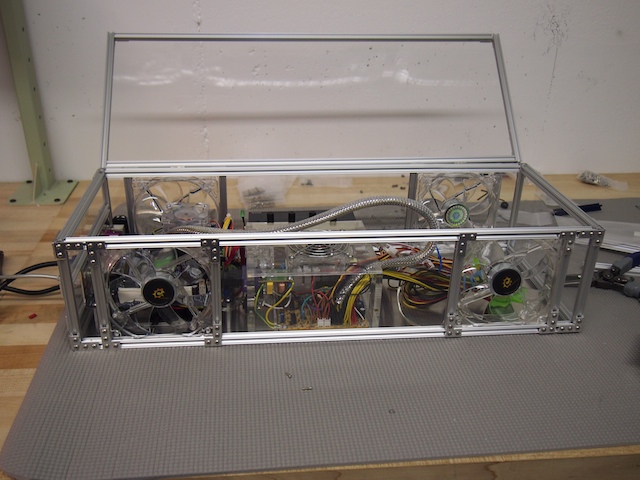
Part of this project is to design and build a custom electronics enclosure that will be a combination computer / CNC / motor control system. This will be the “brain” of the CNC. After trying a few different approaches, we decided to build the box from scratch out of 1/8″ acrylic sheet and Microrax, with are tiny, 10mm 80/20 aluminum beams. The enclosure is about 22″ long, 12″ wide, and 8″ deep. The beauty of Microrax is that we could easily cut the beams to the size we wanted and then use small machine screws and brackets to bolt them together. This allowed us to not only construct the overall enclosure, but to bracket the four cooling fans into place, frame the I/O ports, and add an acrylic lid with hinges. MicroRax is very flexible and cool stuff that I look forward to using for future projects, not only for enclosures, but robots as well.

CNC Electronics Enclosure

On the left side of the enclosure we mounted a mini-ITX motherboard, a small SSD hard drive (not visible in this picture because it’s under the motherboard), the RAM (blue), an internal USB hub, ports for communication with the motor controller, and various other computer components. In the center of the enclosure we installed the main power supply (clear) and the fan control system (black). The right side of the enclosure will contain the motor control boards and other CNC-specific components (which we haven’t installed yet).
There are four main enclosure fans (two on the top and two on the bottom) and four smaller internal fans.
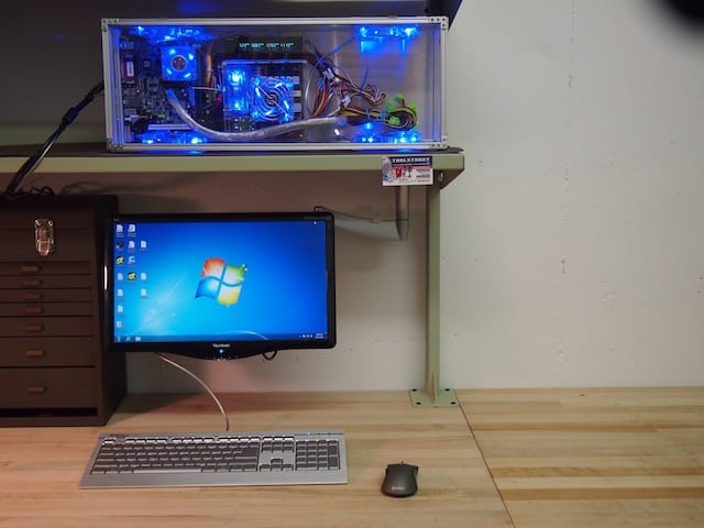
Here is the CNC Electronics Enclosure in the workshop, along with the screen, keyboard, and mouse. We will most likely be mounting the enclosure on the wall so that the lower two fans are more effective.[/caption]
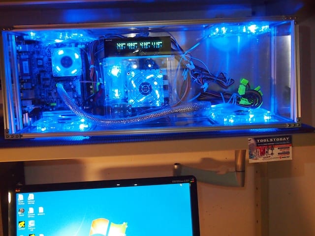
In this close-up, you can see that the fan control system displays the rpm speed of each fan and allows you to adjust it. It also displays the temperature of the corresponding sensor. We’ve attached the sensors to the microprocessor heat sink, the RAM, the motor controllers, and other critical components.[/caption]
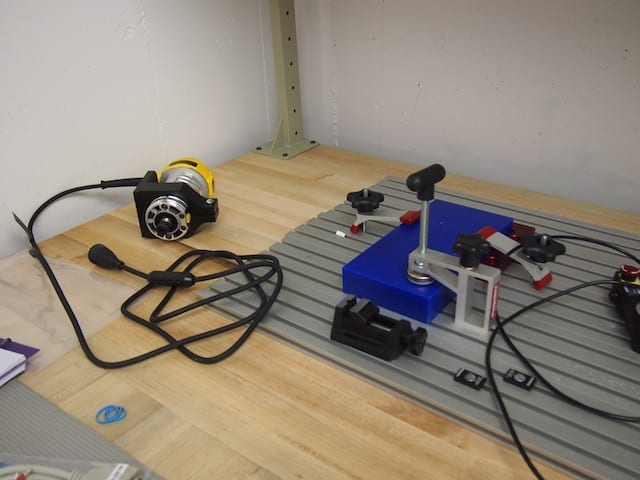
Here are various parts for the CNC that we’ve been working on, including the CNC’s aluminum T-Slot table, various fixtures, the largest of the three interchangeable spindles the CNC will use (for 1/4-inch end mills), and a block of blue machinable wax.
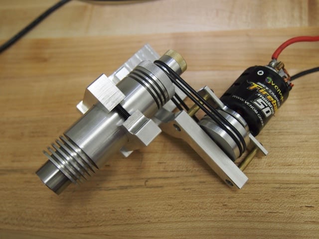
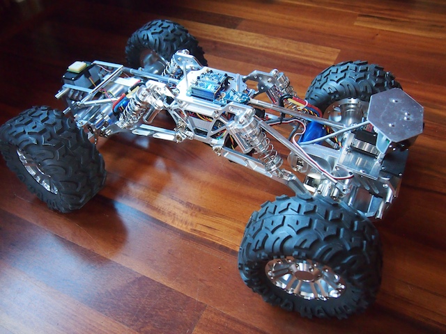
Here is a close up of the smallest spindle the CNC will use. This is a high-precision 1/8-inch spindle for delicate work. It will be driven at a spindle speed of 25,000 rpm by the brushed motor via the two black belts, which in turn will be controlled by the motor controller, which in turn will be controlled by the CNC software running on the computer. At least theoretically! Keep your fingers crossed! :)[/caption]