by Camille | Non-Robot Projects, Workshop Blog
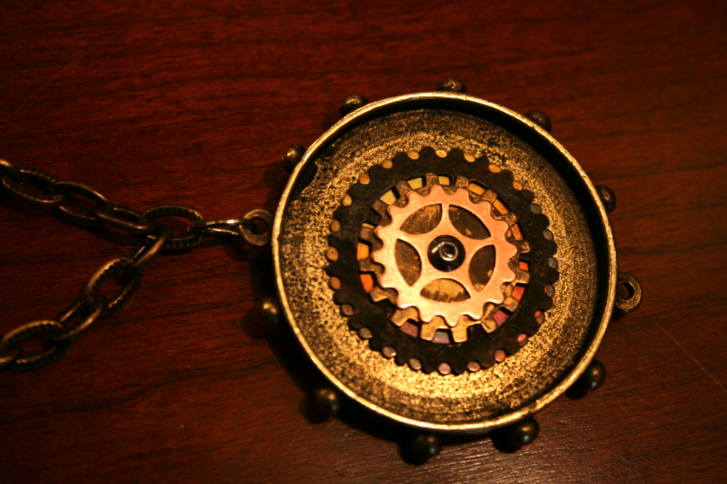
I made this steampunk necklace. The gears, cogs, machine screw, nut, and chain are made out of copper, bronze, steel, and brass. The main round part with little hobnails on it is bronze plated pewter. The little gears and cogs in the middle actually turn, which I think is pretty cool. I was inspired to make this necklace after reading about Tess McKinett’s necklace in my father’s newest steampunk manuscript. Then I made matching copper earrings to go with it. Click on the photos below to see a close up.

Steampunk Necklace

Steampunk Necklace

Steampunk Necklace
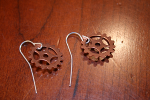
Steampunk Earrings

Camille with Steampunk Necklace and Earrings
by Camille | Gallery, Robots, Slider, Workshop Blog
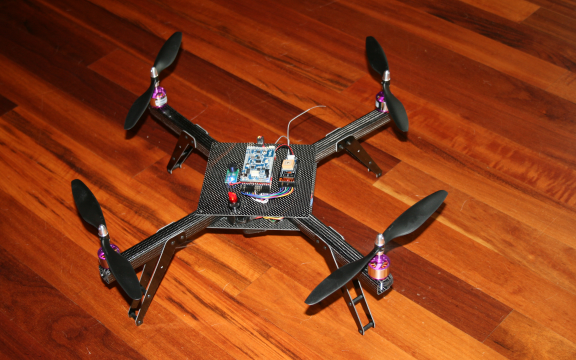
Today, we would like to introduce Black Dragon, our newest flying robot quadrotor. This newest flyer incorporates everything we’ve learned to date about ease-of-use, modular maintainability, crash resistance, lightness, and safety. While we constructed all our previous full-sized quadrotors with aluminum, we designed and built this new flyer with super-cool carbon fiber material. This particular type of carbon fiber, which carries the brand-name “Dragon Plate” (www.dragonplate.com), is used in the aerospace and defense industry, among others. It’s very light, very strong, looks fantastic (the photos don’t do it justice), and is surprisingly machinable.

BLACK DRAGON: Our first carbon fiber quadrotor

Our CAD drawing for the Black Dragon frame design

Our Carbon Fiber Frame

Carbon Fiber Arm. Note that we drilled the motor holes and landing gear holes directly into the arm in order to reduce parts
Like our previous quadrotors, we are using the Arduino-based ArduPilot Mega board as the main controller, a 3-axis Inertial Measurement Unit shield (IMU), a GPS for autopilot navigation, Magnetometer for heading control, and a Sonar for altitude control. The robot can be flown via an RC controller or on various autopilot modes. New features include a large illuminated toggle switch for easy on/off in the field, large main plates to hold electronics and wires, improved frame design, complete elimination of the motor mounts (which used to be susceptible to bending), an x-oriented frame (as opposed to +) to provide an open field of view for a camera mounted on the the front, and improved landing gear.
The carbon fiber material is excellent. We love it. It’s easier to machine and work with than we expected (even with the necessary safety precautions), it’s very attractive, but best of all it’s both very light and very strong. For example, the previous aluminum arms weighed in at about 50 grams each. The new arms are 21 grams each. The whole unit ways in at about 850 grams without the LIPO battery.

Close up view of some of Black Dragon’s electronics
We’ve loaded the software into the microcontroller, calibrated the ESC/motors, double-checked the prop rotation, tested the sonar, set the magnetic declination on the magnetometer, confirmed the GPS is giving good long/lat, and it’s ready to fly. We’ve flown it a few inches off the floor indoors just to make sure it’s good-to-go and so far it seems excellent. Perhaps our best ever. As soon as the rain stops, we’ll be testing it in the big blue sky.
For more details on our various flying drone robots, go here.
I want to give special thanks to the folks at Dragon Plate for sending us their cool material.
by Camille | Workshop Blog
Over the weekend, we built a small Power Distribution Unit for a new robot. We hacked a male Deans connector (which will plug into a high-amp LIPO battery), then soldered it into a marine toggle switch, then screwed it into a device of our own creation. We constructed a miniature power strip with screw terminals to power the various 12 volt electronic components of the robot, such as the motors, Arduino board, IMU, and others. We built it by soldering 8 individual screw terminal pairs to a tiny circuit board that we cut to be just big enough to fit them (about 1.6″ x 0.6″). Then we soldered all the pins on each side together so that voltage will flow down one line and ground will flow down the other. You can see in the picture that we have one small electronic component connected so far. In the past, we’ve just soldered all our power wires together into a big hunk of solder and then heat shrunk the whole thing, but using that approach made it difficult to add new components later on. We think this screw terminal idea will be more flexible by allowing us to add, subtract, and swap components as required.
I don’t understand why some company doesn’t already make a small Power Distribution Unit like this. We aren’t the only ones who need to distribute power to various components. I’ve looked and looked but can’t find anything that’s even close (i.e. small), which is why we decided to build this one ourselves. If anyone has any better suggestions, or has a source for small terminal strips for distributing power, please let us know.
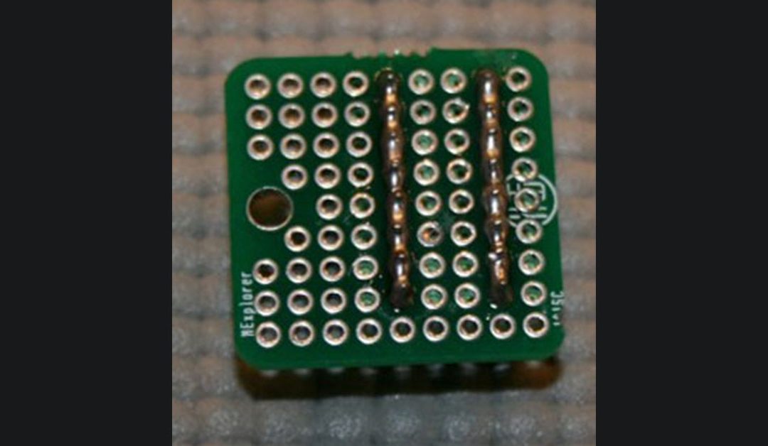
We also built a second screw terminal strip that was even smaller (1″ x 0.6″) for powering up to 8 lower current devices, such as the various 5 volt electronic components. See the pictures of the small green device below, with views of the top and bottom. When we did the soldering, I asked Genevieve to create two long caterpillars of solder along the row of pins. I think she did a very good job.
Building a couple of PDUs is a humble beginning, but every robot has to start someplace. 🙂

Genevieve building Power Distribution Unit

Our homemade mini Power Distribution Unit
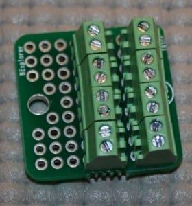
Top Side View of our mini low-amp Power Distribution Unit
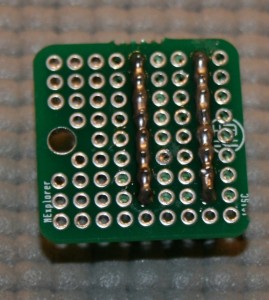
Underside view of the mini PDU showing Genevieve’s soldered “Caterpillars”
