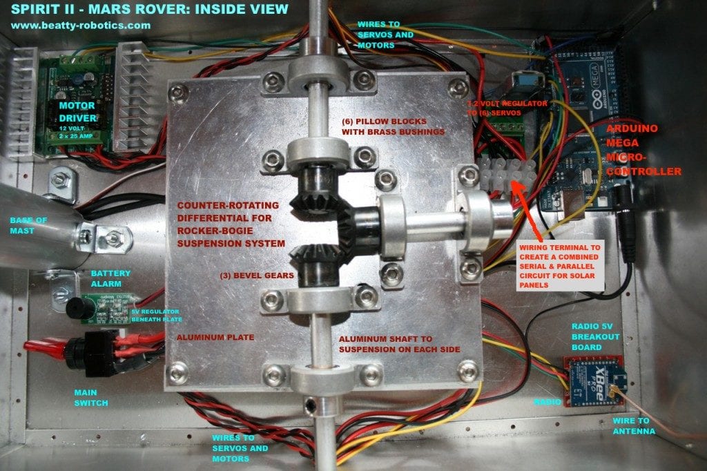
Spirit II Mars Rover

Mars Rover - Side View

The girls and I have always loved the Mars Rover robots Spirit and Opportunity, so we decided we would build one of our own. Today we would like to introduce our Spirit II Mars Rover, which we designed and built in honor of the great Spirit I that explored Mars for more than five years and gathered evidence that there was once liquid water on the Red Planet. The true challenge and fun of building Spirit II was to study and reverse engineer how NASA built theirs. The NASA rovers have several unique and very specific characteristics that we wanted to incorporate into our robot, especially the “rocker-bogie suspension system,” which allows the rover to roll over rocks that are 50% the height of the front

Mars Rover - Corner View

wheel (try that in an automobile!). We watched videos, read the NASA white papers, and even studied their patents. The key to the suspension system was the configuration of the wheels, the multi-jointed swiveling chassis, and a special counter-rotating differential that we built. Mars Rovers also have a very unique way of turning: they use servos to rotate the wheels at each corner 45 degrees, then spin to the desired heading. And, of course, Spirit II is solar powered like the original. Although it was difficult, in the end, we are very pleased with how Spirit II turned out. Enjoy the pictures and video below.


Here are a few construction photos (click the picture to see larger image):

Here we are working on one side of the rocker-bogie suspension system.

Here we're working on the counter-rotating differential and how it connects to the rocker-bogie suspension system. When the robot rolls a front wheel over a large rock, the suspension system tilts upward. The differential turns the rotation in the opposite direction, thereby tilting the opposite side of the robot downward to make sure the robot's center box stays steady and level.

Here we have assembled the back half of the rocker-bogie suspension system.

The Counter Rotating Differential we designed and built for our Mars Rover.

Here we are assembling the wheels, each of which has dozens of pieces. We cut the aluminum shafts, screw the wheel plates together, assemble the universal hubs, attach the treads, and on and on...

Mars Rover - Inside View


Mars Rover postings in our Workshop Blog


Technical Specifics

  • Design and Construction: Beatty Robotics
  • Software: Beatty Robotics
  • Microcontroller: Arduino Mega
  • Aluminum sheet & tubing, gears, fasteners, hardware, and much else: McMaster-Carr
  • Motor Controller: Dimension Engineering Sabertooth 2×12
  • Motors: Lynxmotion
  • Servos: (4) Hitec Digital + (1) Hitec for pancam
  • Servo brackets, hubs & other hardware: Servocity & Lynxmotion
  • Aluminum tubing & hardware: ServoCity
  • Solar Panels, wires, cameras, and much else: Sparkfun
  • Battery: 12V Lithium-Polymer
  • Radio: Xbee
  • Remote Control Hardware & Software: Beatty Robotics
  • Wheels: (6) Vex Robotics
  • Wheel Hubs and other hardware: AndyMark
  • Voltage Regulators: Pololu & Dimension Engineering
  • Relays: DFRobot
  • Differential: Beatty Robotics

32 Comments

  1. AAAAAAWEEEESOOOOMEEEE!!!!!!! Really love it!!!! Like to see even more photos of its inner workings, though! Keep it up! :)

    • We’ve posted a new image that shows the electronics. Click on the photo to see the full-sized photo.

      • Dear colleagues,

        We are writing you on behalf of Student Science Association of Kaunas University of Technology (Lithuania). We would like to invite you to participate in the international contest of robots “Robots’ Intellect 2012″. The event is being organized the second time in the Baltic States. This year contest will be held on May 3rd, 2012 in Kaunas University of Technology campus. The goal… of this competition is to motivate young people to take interest in high technology, artificial intelligence, robotics and other current topical areas of science and technology, as well as to try their personal skills and knowledge in creating their own robots.
        In 2011 no one won the jackpot “The Golden Sack” filled with 9000 Euros, so it was left to grow and wait for the competitors of 2012. MINI gold back is 500 Euros. The main task remains the same as the last year: a robot must find the golden sack on the special track with obstacles and fetch it to the start line. What is more, robots will have a chance to compete in other tasks, such as line tracking, labyrinth and others.
        Also, during this event, there will be robots’ exhibition, in which anyone, who has a robot, even the simplest one, can participate.
        If you are interested, don’t hesitate and register for this competition.
        For more information please visit our website http://www.robotsintellect.lt.
        Contact us if you have any questions, it will be our pleasure to answer.
        We are looking forward to seeing you in the competition “Robots’ Intelligence 2012″, May 3rd, 2012.

        http://www.robotsintellect.lt
        smd@ktu.lt

  2. Amazing!!!! Me and my 5 year old love it.
    He told me the other day that he wanted to build a robot, i think i have just found something we can build. How did you make the wheel plates?

    • Thanks, Alex. When you say you just found something you can build, do you mean the Spirit II or something else (if something else, let me know what it is). The round wheel plates come from the Pro section of Vex robotics.

  3. Hi
    This is the most awesome hobby robot ever!
    I love the way you have done the differential in the middle.
    I had read the descriptions on NASA and Wikipedia sites, but couldn’t figure out how it worked! Your design is so simple and elegant.

    • Thank you, Pete. We appreciate it. We had a lot of fun designing and building the Mars Rover. We are glad that someone appreciates our differential, which we thought was pretty cool. :)

  4. Hi,
    your spirit II is just fantastic…

    Actually, I built one a little less precise approximation of Spirit rover myself. http://robotika.cz/competitions/robotour/2011/teams/moon-rabbit.jpg . It’s called Spirit Junior, and it is a tribute to the now deceased original Spirit…

    For the next year competition I’m building the rocker-bogie drive for it, but I’l make a little different approach. But your differential mechanism is very inspiring. I’m gonna have to make some modelling of it if it is usable in my robot too ( robot has to carry a 10kg off load and I’m not sure how robust I can create this mechanism ), otherwise I make some simple balancing mechanism on the front.

    Great thanks for inspiration
    Kamil

    • Kamil, Very impressive. I like your Mars Rover a lot. Nicely done. What do the sensors on the tower do? (By the way, I like your use of the crawler chassis. We are currently working on a new robot that also uses a crawler chassis)

      • Thanks, it took lot of hours from my past year…

        On the tower there are 2 webcams to detect edge of road, then there is Kinect as obstacle detector. In the box up on the top there is gyro/ accelerometer/ compas.

        The crawler, as it turned out was a good choice for this app. It has great torque at low powerdraw ( it works for 2.5 hours on 7.2V 4.5Ah ). Only thing i was concerned about was the plastic parts of gearboxes, thats one of the reason why I want to change it to rocker-bogie. The other reason is that I always wanted to build a rocker bogie :) .

        Btw, what torque (kg/cm) has those servos you used for steering?

        • Your sensors sound excellent. Is working with the Kinect difficult? Do you have to use a programming environment like .Net or something?

          Regarding servos: I started with these (which is what you see in the video, although they are painted gold): http://www.servocity.com/html/hs-5685mh_servo.html

          They work OK, but they weren’t quite strong enough for rugged outdoor use, so I’ve upgraded to these servos, which are very impressive and stout:
          http://www.servocity.com/html/hs-7950th_servo.html

          Servos of this quality and torque are extremely expensive, but required for the Rover’s unusual steering mechanism. Due to NASA’s original design, there is a big “Moment of Force”(http://en.wikipedia.org/wiki/Moment_(physics)), which the servo has to be able to withstand. When you design your rover, do everything you can to minimize the “Moment Arm” (the horizontal distance from the downward force of the leg and the center of the wheel.)

  5. I started a new comment as it was getting too thin :) .

    The plan is to make the center of the wheel in the axis of ration. And Simmechanics spitted out that for the size and weight of all components ( gear, motor, construnctio itself ) in the maximum acceleration of robot ( 2 m/s/s ), the minimum torque of the servo needs to be at least 0.3Nm. Servos I intend to use are 2.2Nm so it should work…

    And Kinect SDK is .NET, especially for C#, and very easy to use. As I’m a java dev, it is quite enriching experience ;) . In general Kinect works great – very stable. If I will be not able to find another thousand euros for Lidar, I’l buy another one of these to cover wider area ( kinect cover 62 degrees ).

    And data from the Simmechanics on the center differential mechanism is out – torque on robot of my size and weight will be 207Nm, there will be needed a gear with diameter 2″… So I’l rather do some simple balancer on the front…

  6. Compliments to you and daughters on a beautifully designed rover! Favor me one question. The rover internals show one dual amp motor controller driving 6 motors and servos, correct? Kindly explain please…

    • Thank you. We appreciate it. Yes, there is one Dimension Engineering Sabertooth 2 x 12 AMP motor controller. The three motors on the left side are wired together to the controller’s first channel. The three motors on the right side are wired to the second channel. Even though there are 6 motors, it’s not necessary to have three dual motor controllers. You only need one dual motor controller. The motors on a side operate in unison. In addition, there are four high-torque servos, one directly above each corner wheel, that will rotate the orientation of that particular wheel in order to set the wheels at forty five degree angles so that the robot will rotate in place around its center (this is how the NASA rover makes its turns. It actually rotates in place, then goes forward. You can see it doing this in the video). We programmed the Arduino to direct those servos through a tiny servo controller (a Pololu Maestro 6).
      Let us know if you need any more details than that.

  7. we found what I was looking, I am a Brazilian who was eager to build a rover that neither NASA and I think your site. Looks really like
    I wonder how you managed to create and how many days or months it took. Cause I want to create a display in my school project

    very good

    • Matheus, Thank you for your positive comments. The Mars Rover took several months to build. The best place to start is to look at the detailed pictures on this site including links to the other pages (like the interior shots). Then check out all the companies/websites where we purchased the component parts (list at the bottom of the page). The part we’re most proud of is the rocker-bogie suspension system, which we made out of aluminum tubing.

  8. The more or less you spend?

  9. hi remember me, I wonder if you have e-mail, for I want more information about what you used on the robot

  10. What you put down (in box) is counter-rotating differential rocker-bogie suspension system?

    Since already obliged

    • I’m not sure I understand your latest question. The counter-rotating differential is the three bevel gears inside the box. Each set of three wheels (on each of the two sides) is attached to it via an aluminum shaft. The counter-rotating differential is part of the rocker-bogie suspension system (which is visible on the outside of the box as the legs, wheels, connecting tubes, etc.).

    • CustomColor has always done me well no scrtached slides or negs, good prints, etc. I need some med format enlargements done, so I’ll have to pay them a visit in the new spot. Little known fact if you return the boxes that slides come in, they’ll give you $0.15 per box in cash.

  11. But where and how you connected all the wires?

  12. please give me the wheel assembly details

    thank you

  13. please give me the wheel assembly details of spirit mars rover

    thankyou

  14. sir i am very curious to know about the remote control system schematic diagram and as well as on board schematic diagram of mars rover spirit.

  15. Hello again,

    I wrote here about half a year ago, I was looking for inspiration then. Now the robot is almost finished… in the end I reimplemented your differential idea – I call it Beatty’s differential drive ;) and it became an inner joke… See here http://moonrabbit.eu/?p=219 , on the bottom of the page there are some images of it…

    Here is also image of whole rocker bogie – great thanx for inspiration.

    • Hello Kamil. Good to hear from you again. I’ve looked at the work you’re doing. It’s fantastic! Well done. I’ve put a comment on your site. I’m honored to have a differential named after me. That’s cool. :)

  16. I would like to know about the steering mechanism of ther Rocker Bogie. The steering Servo Motors are usually not directly connected to the driving motors, they use some kind of “[” shaped frame. If I am using that design, how do I use the servo to turn the wheel. Directly connecting the servos to the frame is not an option. Please Help. Thanks

Trackbacks/Pingbacks

  1. Spirit II – Mars Rover: INSIDE VIEW | Beatty Robotics - [...] Posted by Robert Beatty on Nov 2, 20110 comments [...]
  2. Mars Rover – Motion Test Video | Beatty Robotics - [...] system worked very well, but as expected, it behaved a little bit differently compared to the first Mars Rover ...

Leave a Comment