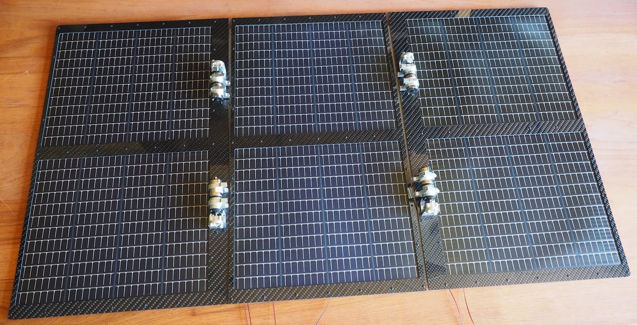
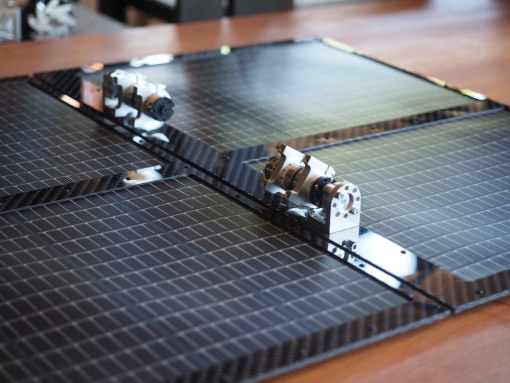
We have been working on the solar top for the Lunar Rover. The rover will use six 15.4V PowerFilm solar panels (PT15-300) to generate a total of 1.2 Amps @ 15.4V, which will be used to charge the 3-cell 12V lithium-ion battery. Each panel is 10.6″ x 12.8″. We selected the PowerFilm panels because they were thin, flexible, rugged, easy to work with, and came in a variety of shapes and sizes. We mounted the panels in between a sandwich of custom-designed, CNC-machined carbon fiber plates that we designed for the purpose. We used carbon fiber (provided by DragonPlate) because it was lightweight and rigid. The plates are held together with small, black, #2-56 screws. Because we wanted the area between the plates to be thin, we didn’t use our normal 24 AWG wire, which was too thick. Instead, we used copper conductive strip, which is flat. When mounted on the robot, two of the panels will be in the central, fixed position. There will also be a pair of panels on “solar wings” on each side. The wings will start out folded on top of the robot’s main body over the two fixed panels. When we want to deploy the solar wings, small motors will open them up like the pedals of a flower, exposing all six panels to the sun. This design allows us to keep the robot compact for transport, but have three times the surface area and therefore three times the current for charging the batteries.
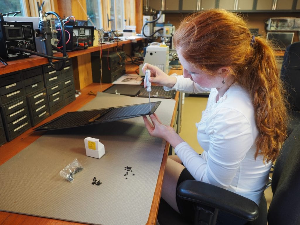
ASSEMBLING THE SOLAR PANELS BETWEEN THE CARBON FIBER PLATES
WE USED CARBON FIBER TO MINIMIZE WEIGHT, BUT MAXIMIZE RIGIDITY IN THE SOLAR WINGS
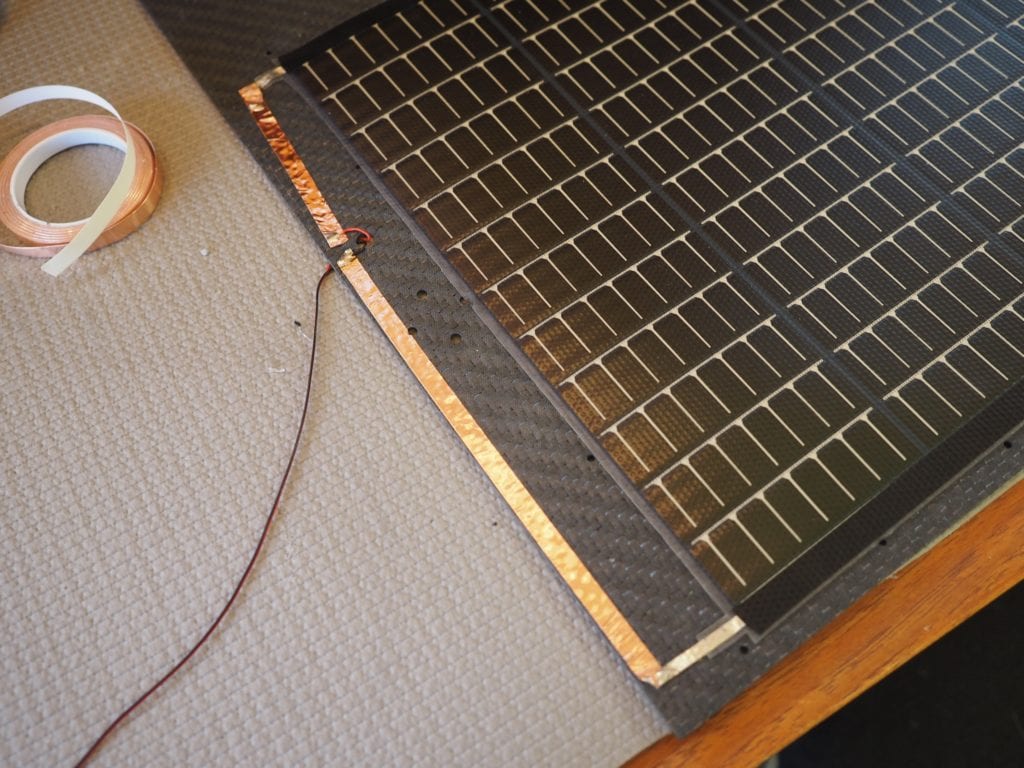
TO KEEP IT FLAT, WE USED CONDUCTIVE COPPER STRIP RATHER THAN WIRES. THE “FINGERS” (SHORT LINES) OF THE SOLAR PANEL POINT TOWARD THE NEGATIVE SIDE. THE “KNUCKLES” ARE ON THE POSITIVE SIDE.
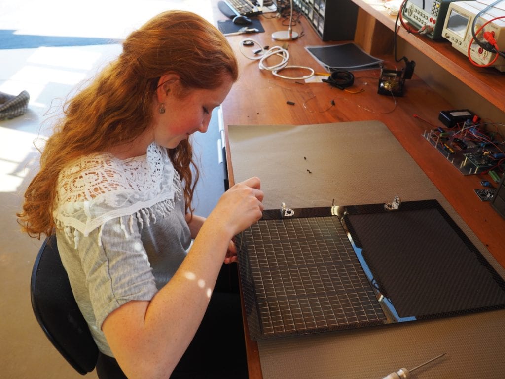
WHEN THE SOLAR WINGS ARE MOUNTED ON THE ROBOT, THESE SMALL MOTORS WILL BE USED TO OPEN THE WINGS
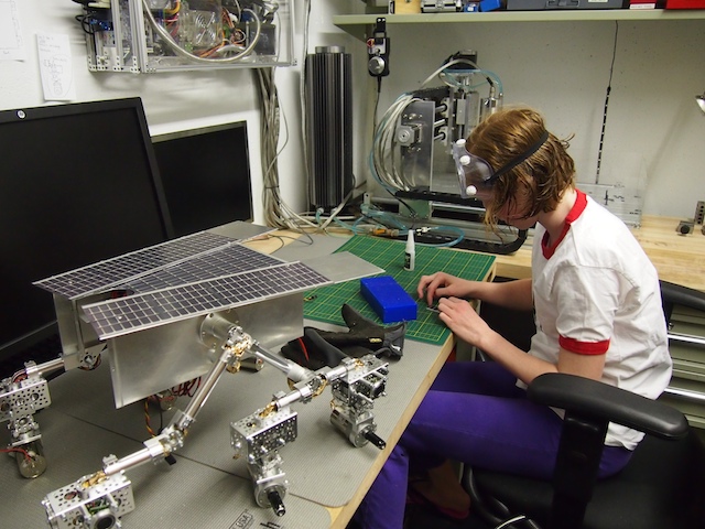
We’ve been busy working on the new Mars Rover. Over the last few days we’ve been focused on the chassis, the thin-film solar panels for the top, the mast, and aligning the servos for steering. Pics below.
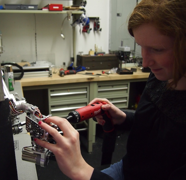
Here I am using my new power driver to work on the robot’s chassis. This is now my favorite tool.
Working on assembling the solar panels that will cover the top deck of the Mars Rover.
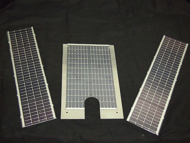
The completed “solar wings” and top deck. These are actual thin-film solar panels attached to custom-machined aluminum plates.
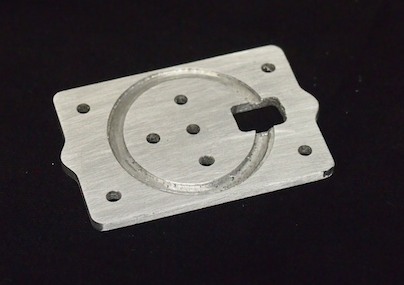
We ran into a particular challenge when it came time to build the mast. In the end, we decided to design and machine a custom servo plate using the CNC. The top of the plate will hold the pan servo. The bottom of the plate will hold the shaft tube (using a circular slot).
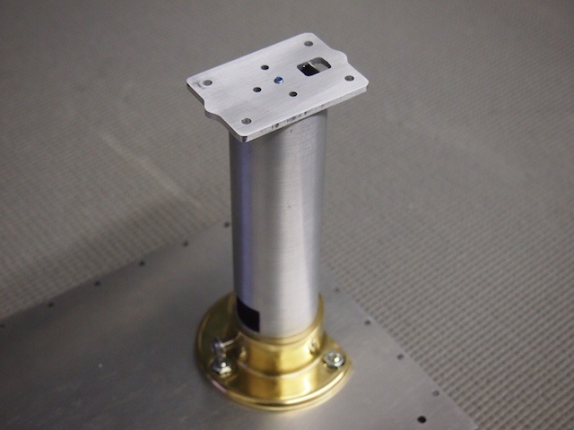
The custom servo plate mounted on the mast. The plate is held down with a threaded rod that goes down through the mast and threads into the bottom of the rover.
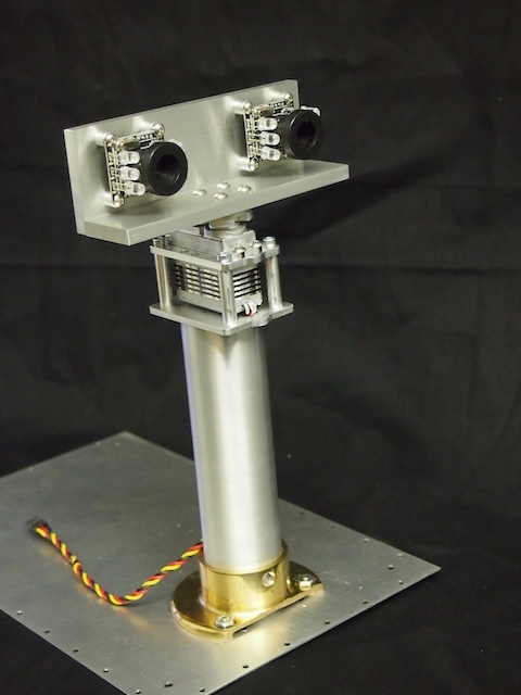
Here is the completed mast assembly. From the bottom up: The robot’s bottom plate, the mast flange, the mast tube, the custom servo plate, the pan servo, the top servo plate, the servo horn, and the mast head, which is made out of two custom machined plates of aluminum.
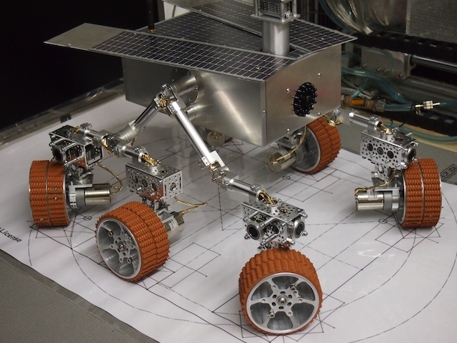
In order to align and calibrate the steering servos we created a special, full-scale drawing that indicates where the wheels should be at each of the various steering positions. This really helped center the servos properly.
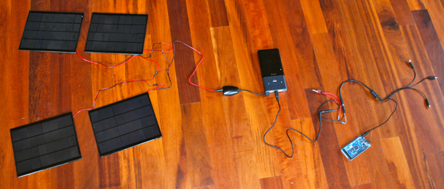
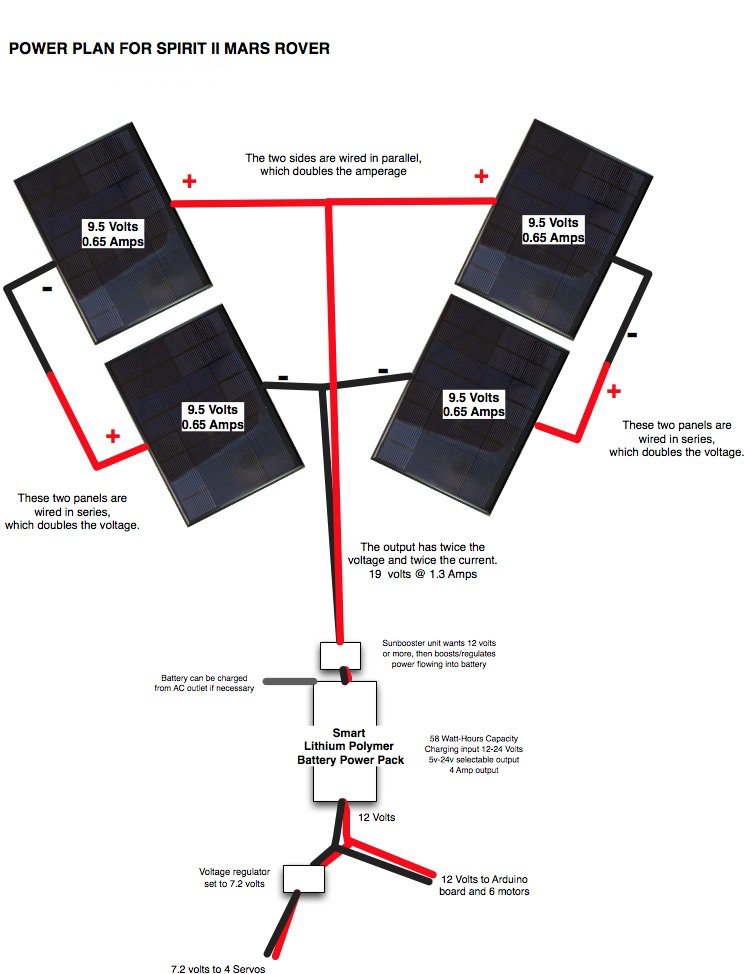
We’ve been working on the power system for our Spirit II Mars Rover, which, like the real Spirit robot on Mars, will be solar powered. We plan to use four small solar panels. Each one is about 7″ x 9″ and delivers about 9.5 Volts / 0.65 Amps / 5.2 Watts.
We wired two pair of panels into a series circuit to double the voltage of the output, then wired the pairs together into a parallel circuit to double the current amperage. We the combined unit to a little voltage regulator that feeds a lithium polymer smart battery, which in turn will feed the electronics, motors, and servos of the Mars Rover robot.
Today we wired the panels in series/parallel, hooked everything together, and powered our main Arduino microcontroller. It worked and it was very cool!