by Camille | Workshop Blog
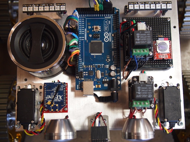
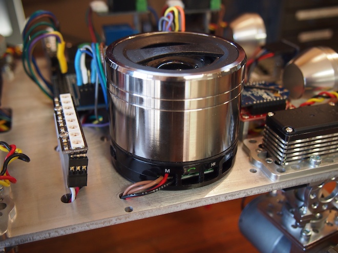
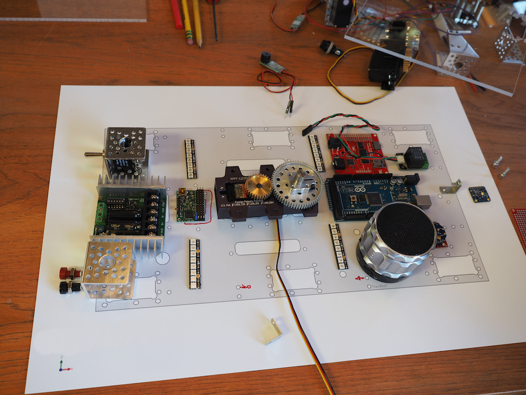
We often add sound effects and even music to our robots. We’ve used a number of approaches, but our latest method is the SOMO-II MP3 Module. Here are some pictures (from a rover robot we’re working on) and the technical details of how we integrated the SOMO module. First, here is a top view showing the speaker on the left, the Arduino in the middle, a stack of relays, and the SOMO (orange and silver colored square) on the right.
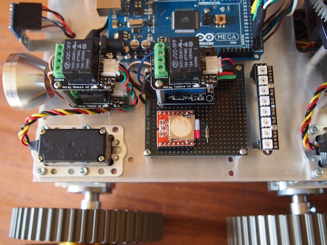
A closer view of the SOMO mounted on female headers soldered to a black protoboard. You can see the microSD card sticking out, which will give you an idea of how small the SOMO is. You can also see the 1K Ohm resister, which is required to get it to work.
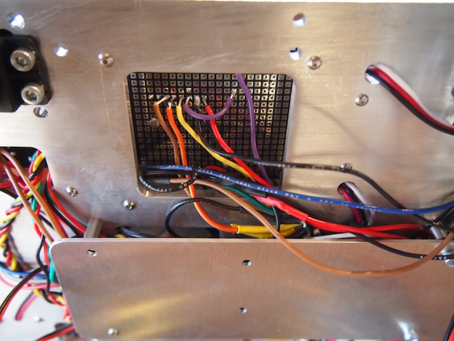
The underside of the prototype board. The SOMO is using the brown, orange, yellow, purple, black, and red wires. The other wires are unrelated.
We took a powered USB speaker apart, hacked into it, and screwed it to the main plate. We pulled out the speaker’s battery and wired the speaker into the robot’s main 5V battery. We also rewired the speaker’s buttons so that we could control its functionality using an Arduino-controlled relay to change its mode so that it will receive an incoming external audio signal.
Here are the steps to get the SOMO setup: First, put your mp3 sound files onto a microSD card. The files should be in a folder called “01”. And they should be numbered 001xxxxx.mp3, 002xxxxx.mp3, and so on, where xxxxx is any name you want to give them (or no name at all, just the number prefix). The main thing is that the files need to begin with the numeric sequence as shown. Next, wire the SOMO to your Arduino and a powered speaker like this. We used Arduino pin 38 and 40 on our Arduino Mega, but you can use whichever suitable digital pins you wish to (or Serial1, Serial2, or Serial3 on a Mega).
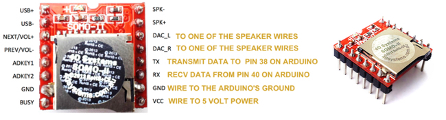
Important Note: The SOMO operates at 3V. If your Arduino operates at 5V (which most do), then solder a 1K ohm resistor on the SOMO’S RX Line. For the speaker, purchase a small, powered USB speaker and cut open the stereo audio cable. You’ll see three wires: white, yellow, and orange. Solder the white wire to the project’s ground. Solder the other two wires to DAC_L and DAC_R. These provide “line out” for a stereo headphone jack, external powered speaker, or amplifier. If you are using a small, non-powered speaker, then use SPK- and SPK+ instead.
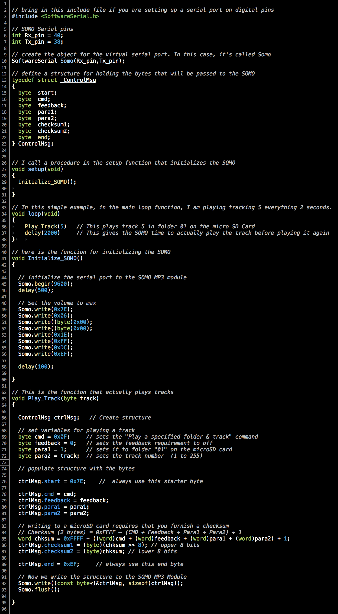
The Arduino source code was the trickiest part. We couldn’t find any libraries or examples of using the SOMO with Arduino, so we wrote our own. Thank you to Curtis Whitley for helping us to figure out how to calculate checksums. At the bottom of this post, we’ve provided a sample program that shows how to play an mp3 track from the microSD card. It provides an example of exactly how to operate the SOMO-II from an Arduino.
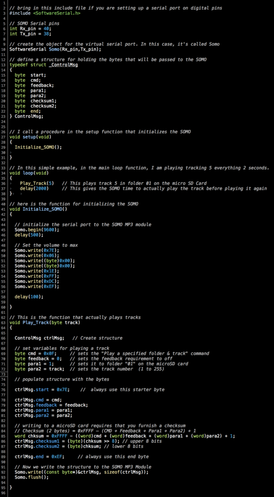
If you wish to copy and paste, grab the code out of this file.
by Camille | Workshop Blog
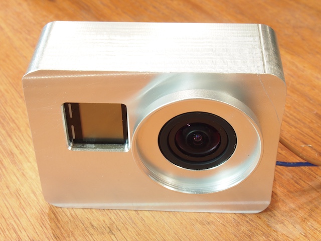
We are in the process of mounting a GoPro camera onto our latest robot. In our previous post we showed how we hacked into the GoPro and wired it up so that we could control it from the robot’s Arduino microcontroller. The next task was to design and machine a case for it. As usual, the CAD design work took longer than the actual machining. It was a fun and challenging little machining project. The end result isn’t perfect, but I think it came out pretty nice, and it will definitely serve the purpose. Our case needed to have these characteristics:
- Protect the GoPro and make it look cool on the robot.
- Provide slots for running the remote control wires.
- Cover up all the GoPro’s buttons so that museum participants and technicians can’t play with the buttons (and mess up the settings in the camera). The camera will be entirely controlled by the robot.
- Provide specialized tapped mounting holes for specific placement on the turret of our robot.
- Provide a lens cover to protect the GoPro’s lens.
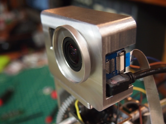
- Provide space and protection for the HD transmission cable and modified USB cable plugged into the side ports.
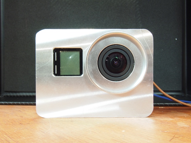
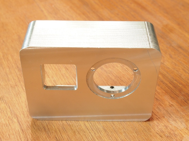
FRONT VIEW OF CAMERA IN CASE
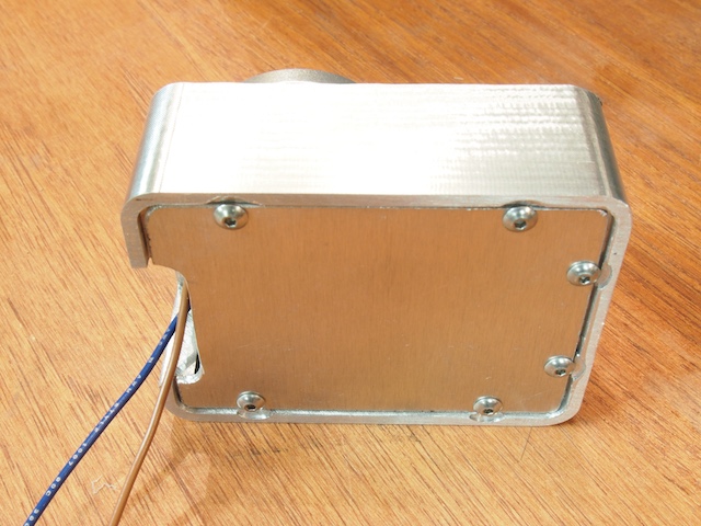
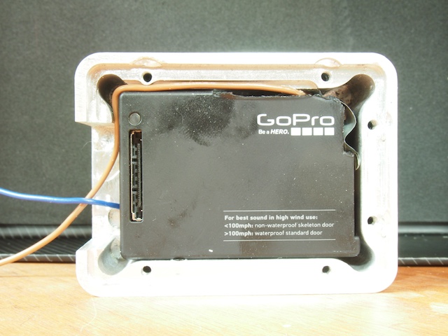
REAR SIDE WITH REMOVABLE PLATE
CORNER VIEW SHOWING HD CABLE AND USB CABLE PLUGGED INTO PORTS
EMPTY CASE BODY MACHINED ON CNC
REAR OF THE CASE BODY SHOWING WIRE SLOTS AND OTHER DETAILS

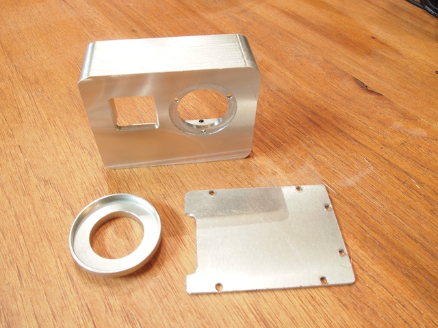
THREE COMPONENTS OF THE CASE (2 custom machined parts + a lens circle hacked from something else)
REAR VIEW – CAMERA IN CASE
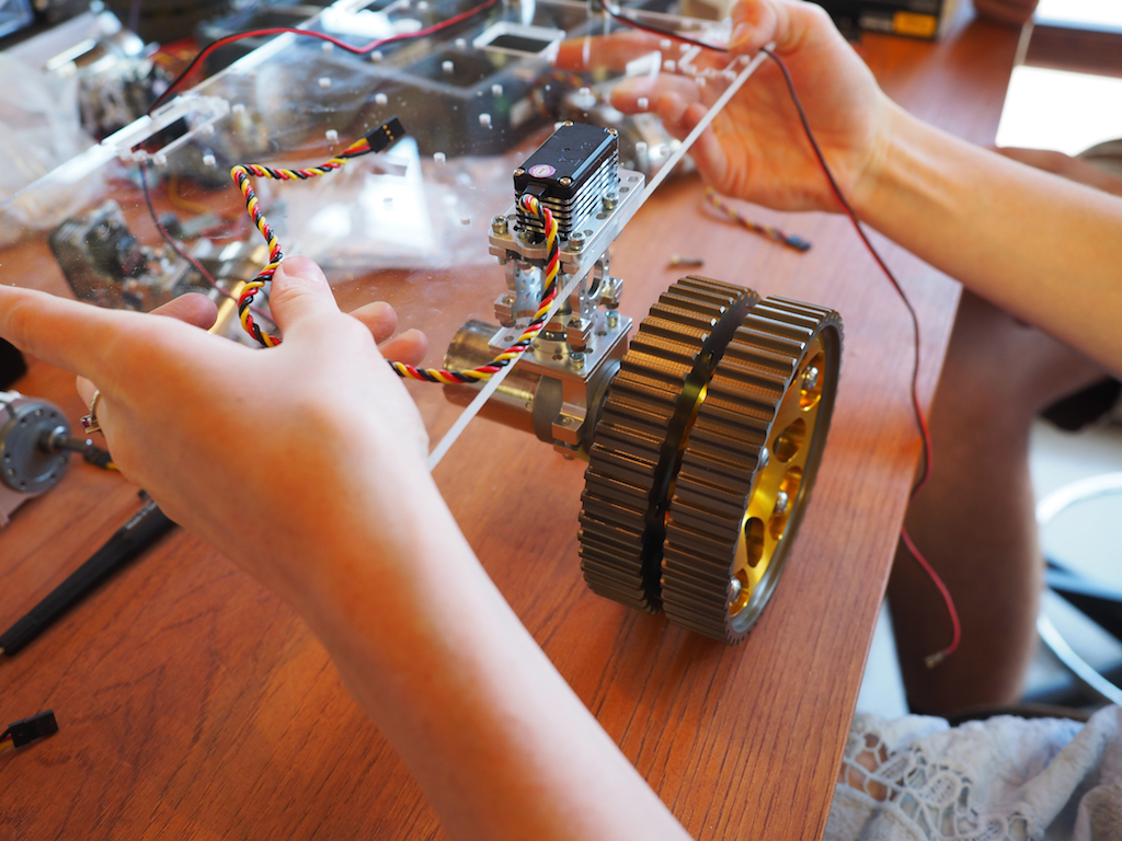
by Camille | Robots, Workshop Blog
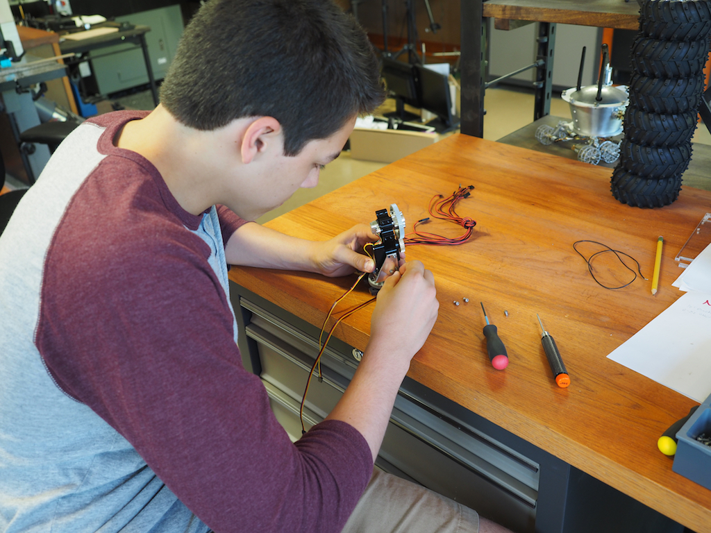
We have taken on a new project to build a compact rover for the New York Hall of Science, something that visitors can drive around in the corridors of the Science Center and that the staff can easily take to off-site activities such as schools and children’s hospitals. The design and construction is well under way. We are also happy to announce that we have a new member at Beatty Robotics. His name is Camille McCollough. He’s a junior at Carolina Day School, where he is taking robotics classes, as well as physics, math, and other curriculum. He has joined our team to learn, gain experience, and lend a hand. Here is Camille building the robot’s pan-tilt turret from Actobotics parts, including a servo, gearbox, and gears:
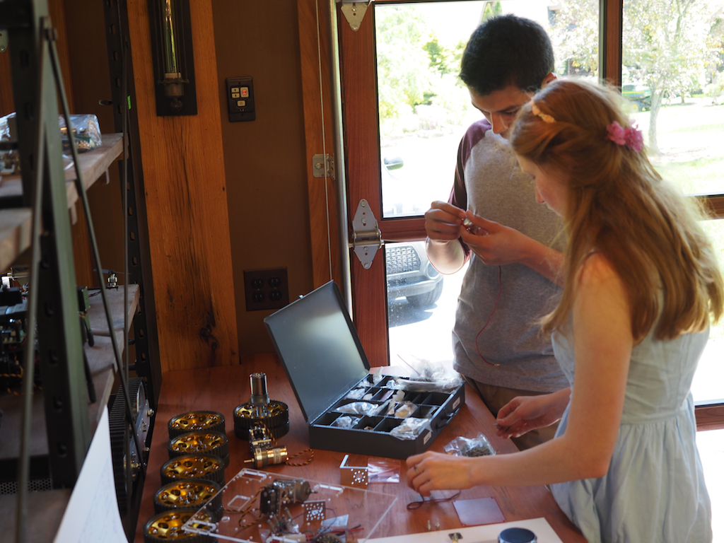
Camille and Camille working on the assembly of the robot’s front LED “head lights”:
Camille working on the assembly of the sonar mounts, while Camille works on the pan-tilt turret:
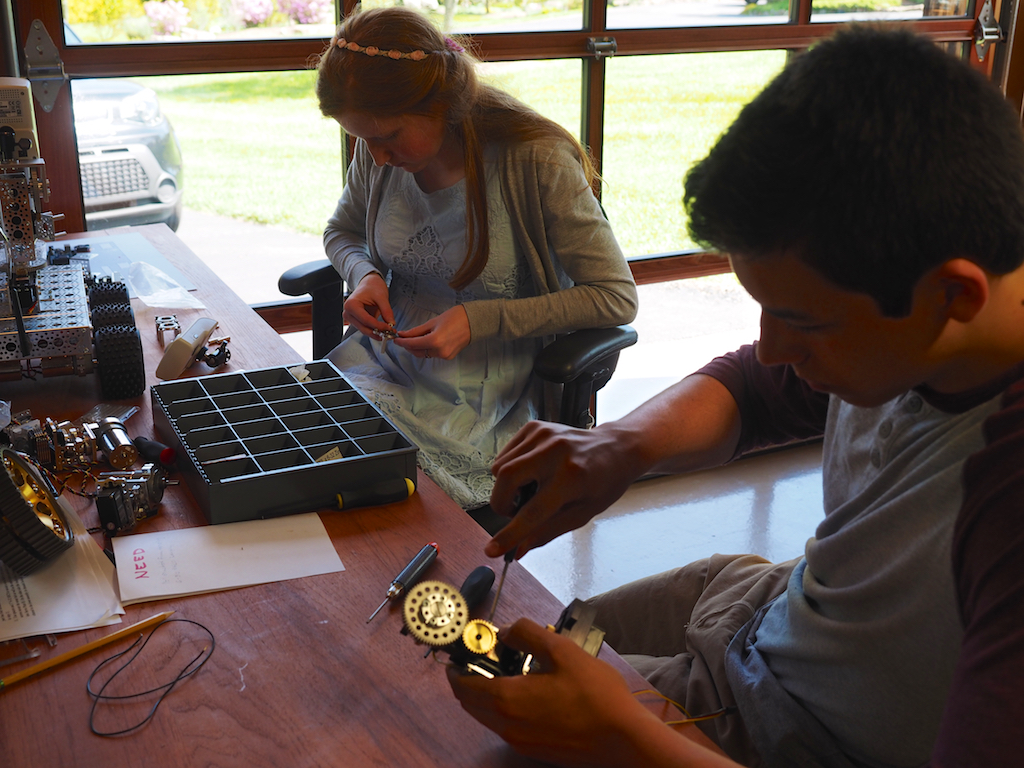
Camille building the first of the six steering assemblies, each of which consists of a servo, servo block, motor, hub, and wheel. We are using a combination of Actobotics parts and our own parts that we made on the CNC.
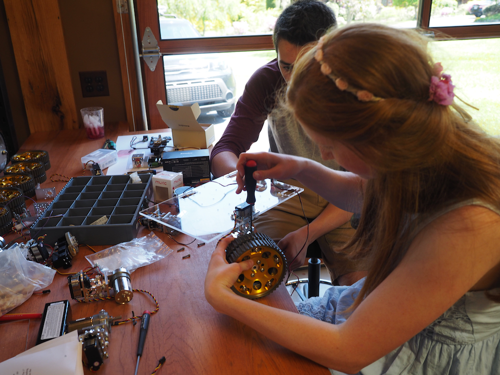
Camille tests the design and assembly of the first steering servo and wheel.
We use a scale drawing of the master plate to plan out where all the components are going to be positioned.
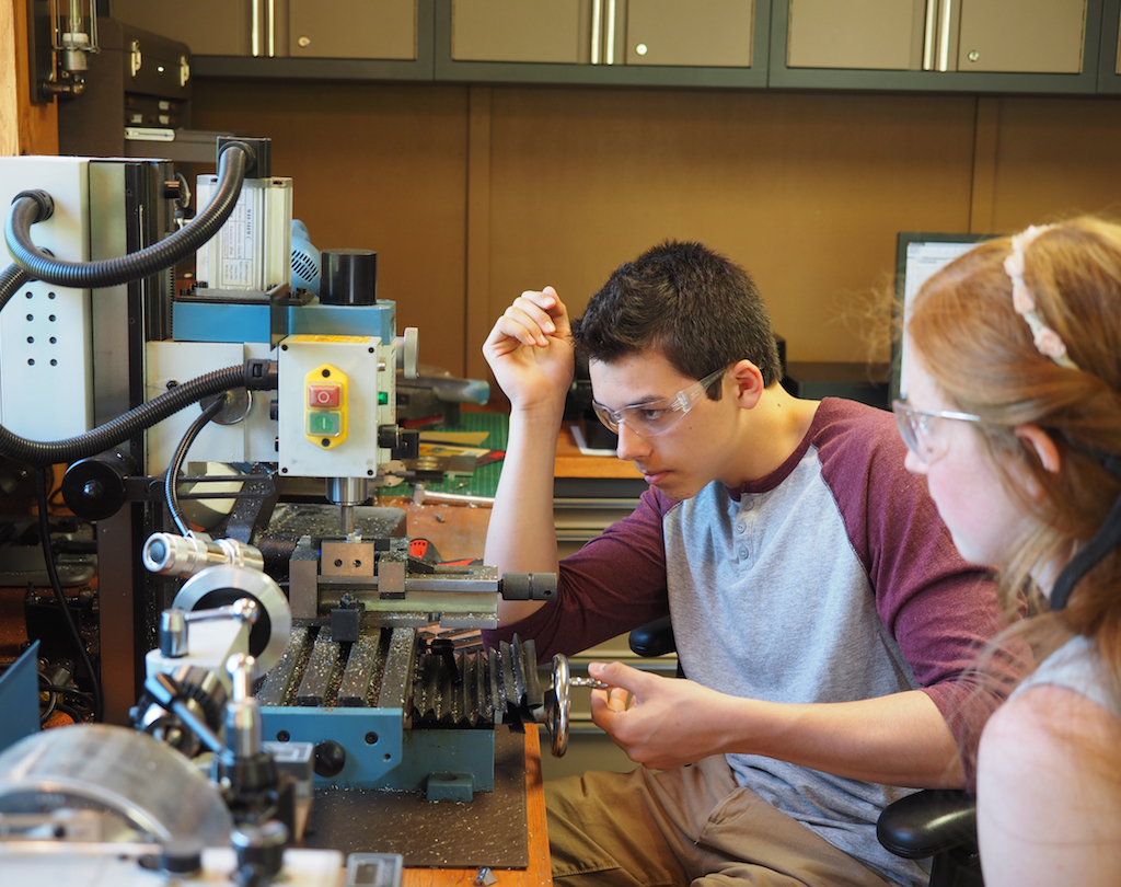
Camille shows Camille how to machine a part of the vertical mill.

Camille machines the next part on the vertical mill.
by Camille | Workshop Blog
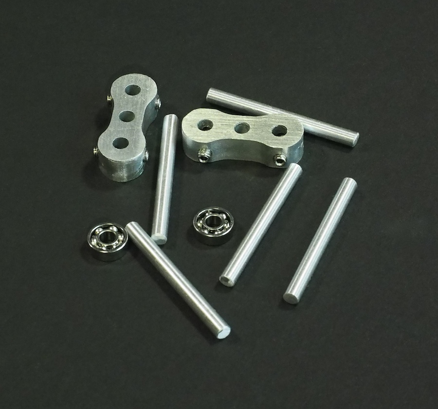
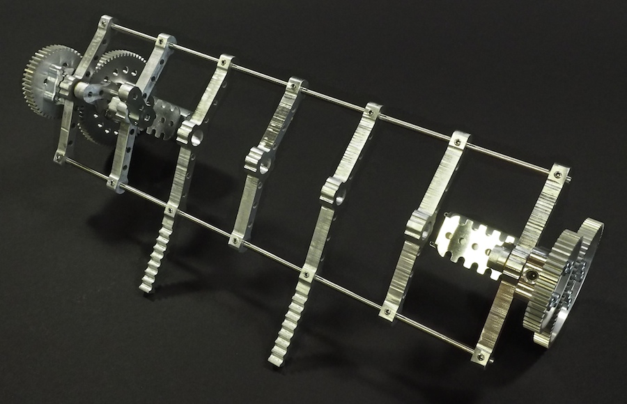
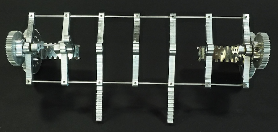
We had good success with our 16-legged walking creature Aluminalis, so we decided to use what we learned and build a new walking creature. We plan for this to be a much smaller, faster, and more agile little beastie. We call her Alumini (Ah-lu-min-ee). Instead of 22″ wide, she’ll be just 10″ wide. Instead of using bulky rectangular segments, we’ve designed much finer segments, like bones in a spine, with built-in pockets for ball bearings to hold the all-important crankshafts. We’ve also designed a custom motor-and-gear mount for each end that holds everything together. Alumini will have twelve legs instead of sixteen. And instead of having a large visible thorax (body), all the electronics will be integrated within and beneath the legs of the robot, so she’ll appear to be nothing but legs. Here are some pictures of our work-in-progress. The crankshaft and legs are not shown. We’re just working on the skeleton and overall structure at this point.
PARTIALLY-CONSTRUCTED SKELETON
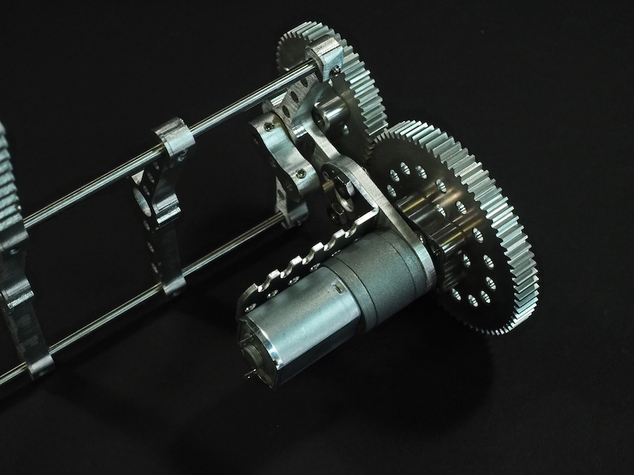
MOTOR AND GEARS MOUNTED ON CUSTOM END PIECE
SKELETON TOP VIEW
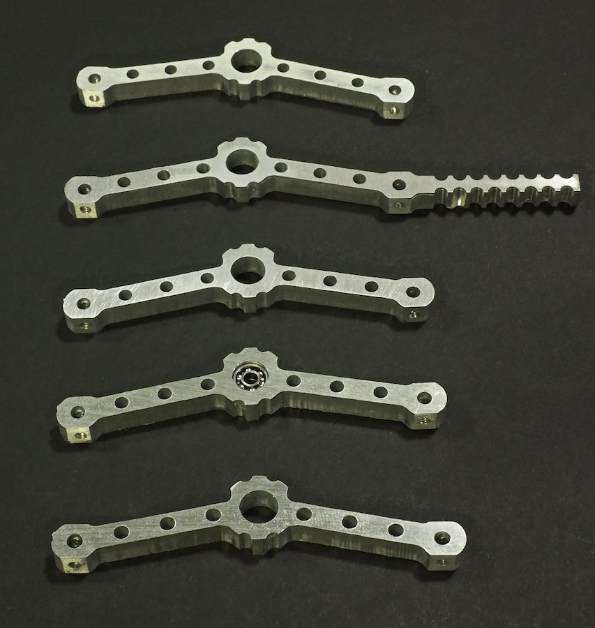
BONE-LIKE SPINE SEGMENTS MACHINED ON CNC
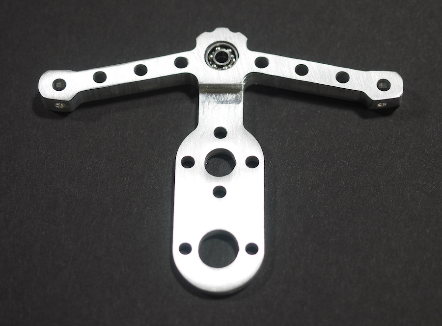
SPINE SEGMENT WITH BALL BEARINGS (TO HOLD CRANKSHAFT) INSTALLED IN SPINE

CLOSE-UP OF MOTOR-AND-GEAR MOUNT
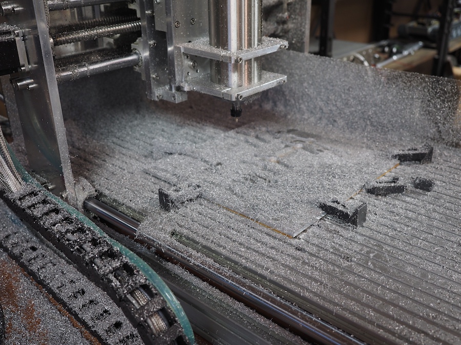
CNC COVERED IN CHIPS AFTER MACHINING THE PARTS FROM A 12″ x 12″ SHEET OF 1/4″ THICK 6061 ALUMINUM
CNC-MACHINED CRANKSHAFT ARMS ALONG WITH BALL BEARINGS AND SHAFTS