by Camille | Non-Robot Projects, Workshop Blog
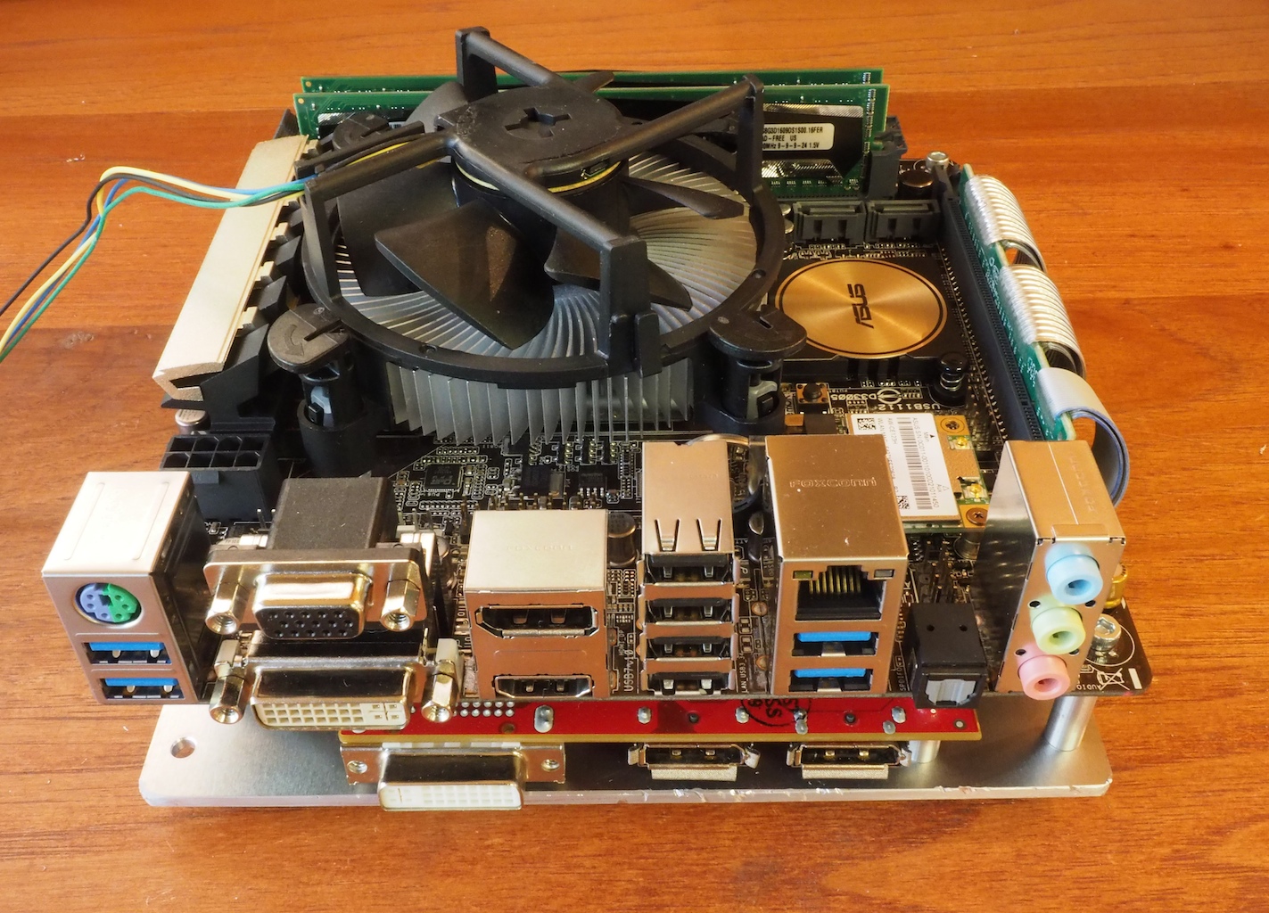
At Beatty Robotics, we love building custom computers. Our latest computer project is a “Mini CAD System” for doing Computer Aided Design. Our goal was to build a small, but very powerful computer for running Solidworks and our CAM software HSMWorks. The computer required a super-fast CPU, a discrete Solidworks-approved graphics processor, plenty of RAM, a SSD hard drive, and the ability to run Windows 7 or 8 (Solidworks requires Windows). We also wanted to be able to customize the computer and overclock the processor to maximize its speed. After doing the necessary research to make sure everything was going to fit our requirements and work together without compatibility problems, we selected these components:
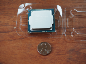
Intel i7-4790K CPU (4.0 Ghz / boost to 4.4 Ghz)
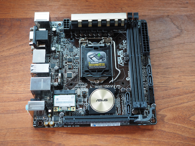
Asus Z971-PLUS Mini-ITX motherboard

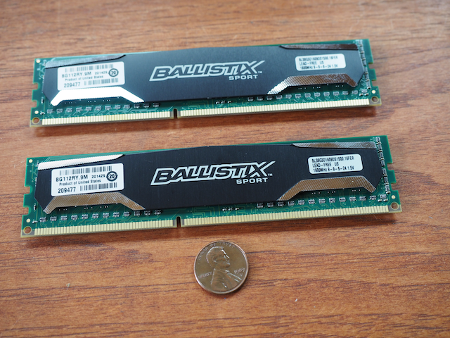
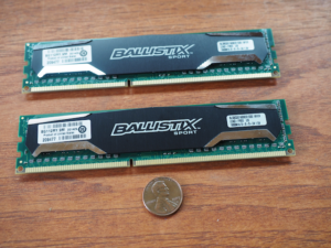
16GB RAM (Crucial Ballistix)
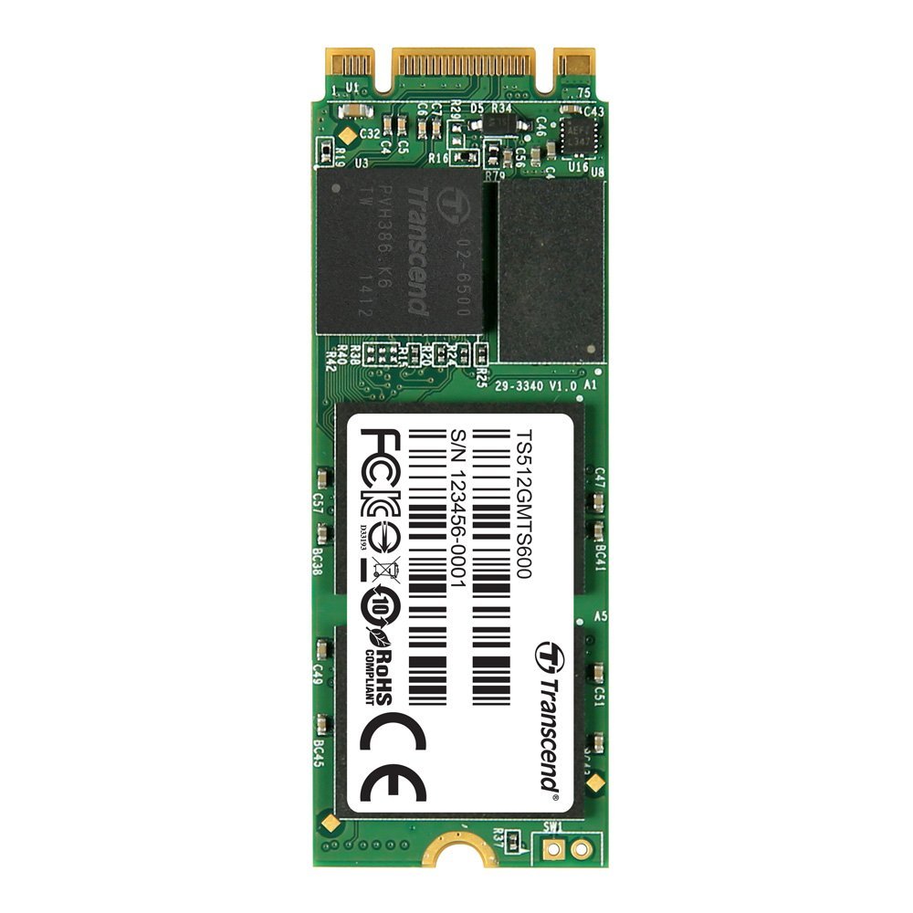
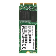
512GB Transcend M.2 Solid State Drive (SSD)
It’s hard to tell from this picture, but this “hard drive” is TINY, just .86″ x 2.36″ x .088″. It fits into a slot on the underside of the motherboard. Incredible.
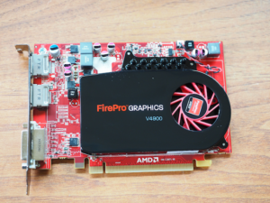
Sapphire AMD FirePro V4900 PCIe Graphics Processor
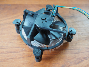
Intel CPU Fan
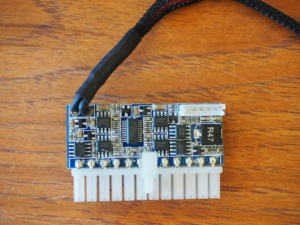
Streacom ST-NANO150 Power Supply
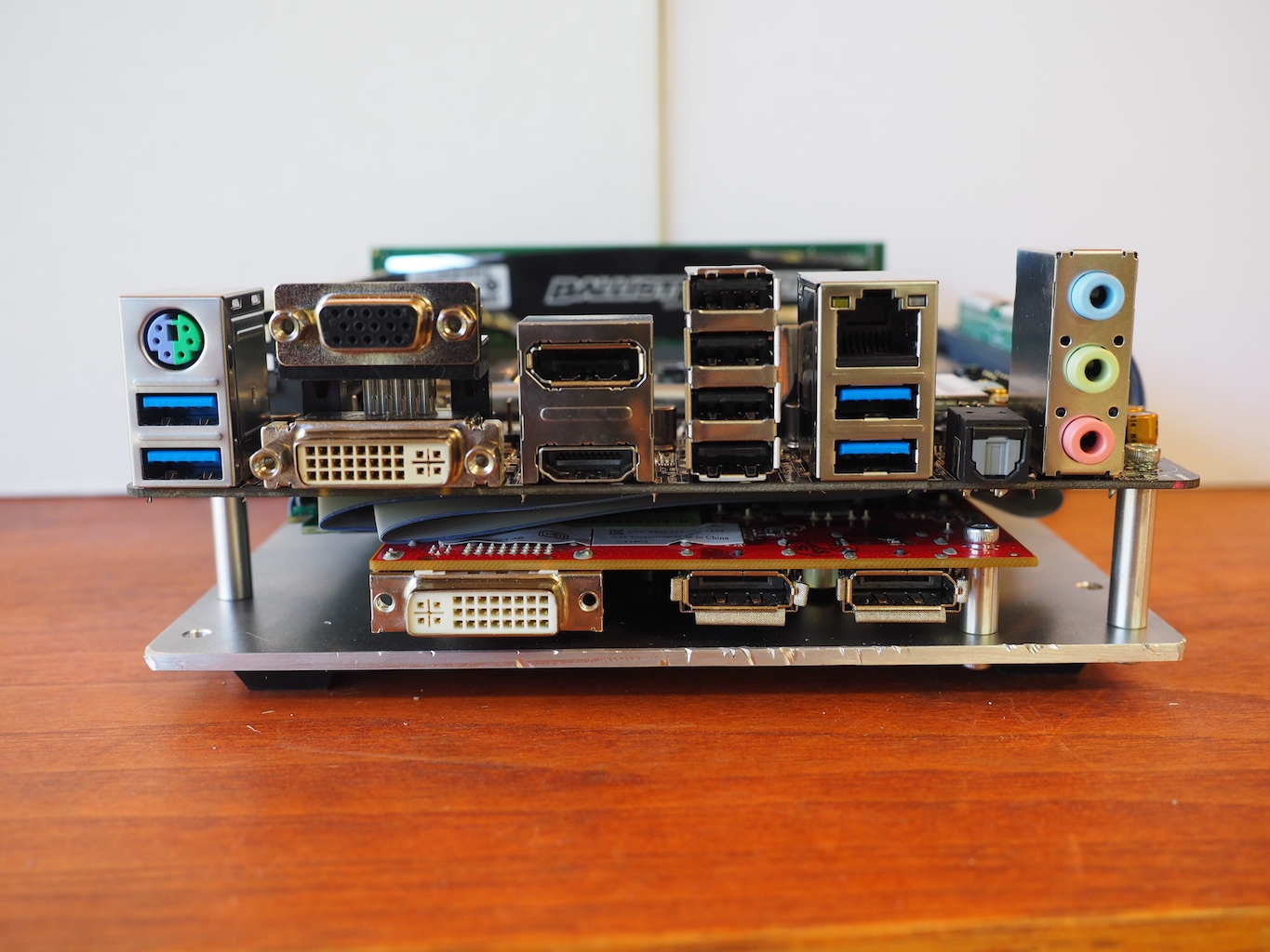
We have the computer assembled, configured and running. Here’s what it looks like so far. We’ve mounted everything on a sandwich of metal plates that we machined. In order to reduce the overall height of the computer, we mounted the graphics card horizontally beneath the motherboard and used a long PCIe “riser” cable. We’ve never seen this done before, but we’re hoping it will work. Everything seems to run fine, including SolidWorks.


So far, so good. It’s 6.7″ square, which is very small for a fast, powerful CAD system. The next step is to build a case for it. There are many excellent commercial cases available for Mini ITX motherboards, but most of them have lots of extra space for a large power supply, conventional hard drives, and an optical drive, all of which we’ve eliminated from our design. The cases that are very small don’t have space for the graphics card. So, we decided it would be fun to design and machine our own small case using our CNC. We haven’t started that part yet, but we’ll keep you posted on how it goes.
by Camille | Non-Robot Projects, Tools and Workshop, Workshop Blog
Up to this time, we’ve been using hand tools to build our robots. But over the last few months, we’ve been working on building a Computer Numerical Control Machine (CNC) that will allow us to precisely cut, drill, and machine aluminum, brass, plastic, wood, and other materials.
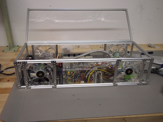
Part of this project is to design and build a custom electronics enclosure that will be a combination computer / CNC / motor control system. This will be the “brain” of the CNC. After trying a few different approaches, we decided to build the box from scratch out of 1/8″ acrylic sheet and Microrax, with are tiny, 10mm 80/20 aluminum beams. The enclosure is about 22″ long, 12″ wide, and 8″ deep. The beauty of Microrax is that we could easily cut the beams to the size we wanted and then use small machine screws and brackets to bolt them together. This allowed us to not only construct the overall enclosure, but to bracket the four cooling fans into place, frame the I/O ports, and add an acrylic lid with hinges. MicroRax is very flexible and cool stuff that I look forward to using for future projects, not only for enclosures, but robots as well.

CNC Electronics Enclosure

On the left side of the enclosure we mounted a mini-ITX motherboard, a small SSD hard drive (not visible in this picture because it’s under the motherboard), the RAM (blue), an internal USB hub, ports for communication with the motor controller, and various other computer components. In the center of the enclosure we installed the main power supply (clear) and the fan control system (black). The right side of the enclosure will contain the motor control boards and other CNC-specific components (which we haven’t installed yet).
There are four main enclosure fans (two on the top and two on the bottom) and four smaller internal fans.
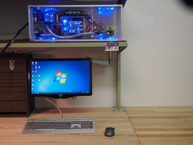
Here is the CNC Electronics Enclosure in the workshop, along with the screen, keyboard, and mouse. We will most likely be mounting the enclosure on the wall so that the lower two fans are more effective.[/caption]
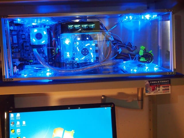
In this close-up, you can see that the fan control system displays the rpm speed of each fan and allows you to adjust it. It also displays the temperature of the corresponding sensor. We’ve attached the sensors to the microprocessor heat sink, the RAM, the motor controllers, and other critical components.[/caption]
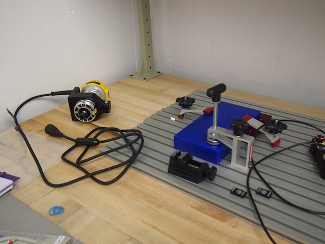
Here are various parts for the CNC that we’ve been working on, including the CNC’s aluminum T-Slot table, various fixtures, the largest of the three interchangeable spindles the CNC will use (for 1/4-inch end mills), and a block of blue machinable wax.
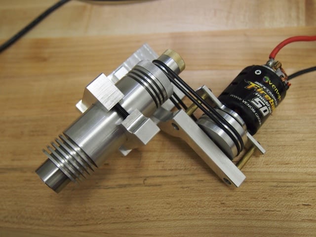
Here is a close up of the smallest spindle the CNC will use. This is a high-precision 1/8-inch spindle for delicate work. It will be driven at a spindle speed of 25,000 rpm by the brushed motor via the two black belts, which in turn will be controlled by the motor controller, which in turn will be controlled by the CNC software running on the computer. At least theoretically! Keep your fingers crossed! :)[/caption]