Using the SOMO-II MP3 Module with Arduino
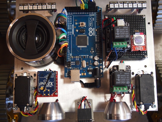
We often add sound effects and even music to our robots. We’ve used a number of approaches, but our latest method is the SOMO-II MP3 Module. Here are some pictures (from a rover robot we’re working on) and the technical details of how we integrated the SOMO module. First, here is a top view showing the speaker on the left, the Arduino in the middle, a stack of relays, and the SOMO (orange and silver colored square) on the right.
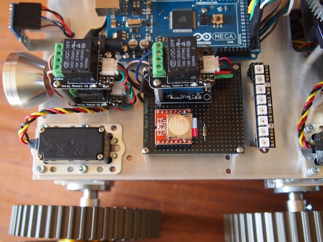
A closer view of the SOMO mounted on female headers soldered to a black protoboard. You can see the microSD card sticking out, which will give you an idea of how small the SOMO is. You can also see the 1K Ohm resister, which is required to get it to work.
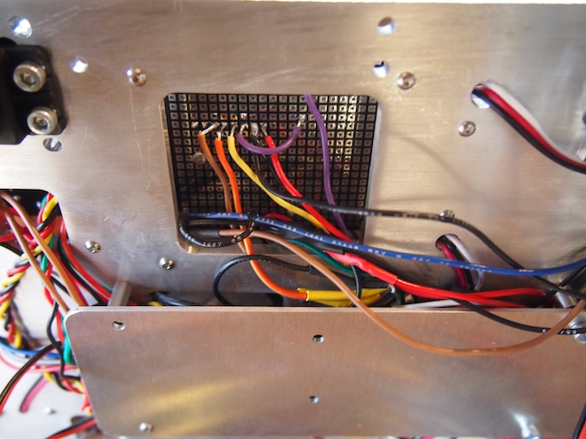
The underside of the prototype board. The SOMO is using the brown, orange, yellow, purple, black, and red wires. The other wires are unrelated.
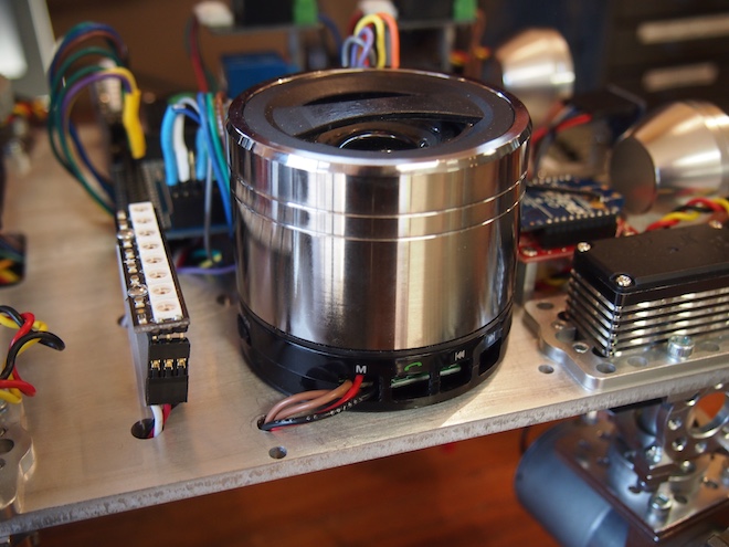
We took a powered USB speaker apart, hacked into it, and screwed it to the main plate. We pulled out the speaker’s battery and wired the speaker into the robot’s main 5V battery. We also rewired the speaker’s buttons so that we could control its functionality using an Arduino-controlled relay to change its mode so that it will receive an incoming external audio signal.
Here are the steps to get the SOMO setup: First, put your mp3 sound files onto a microSD card. The files should be in a folder called “01”. And they should be numbered 001xxxxx.mp3, 002xxxxx.mp3, and so on, where xxxxx is any name you want to give them (or no name at all, just the number prefix). The main thing is that the files need to begin with the numeric sequence as shown. Next, wire the SOMO to your Arduino and a powered speaker like this. We used Arduino pin 38 and 40 on our Arduino Mega, but you can use whichever suitable digital pins you wish to (or Serial1, Serial2, or Serial3 on a Mega).
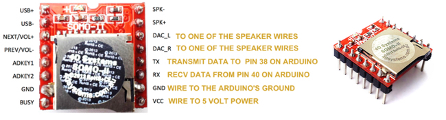
Important Note: The SOMO operates at 3V. If your Arduino operates at 5V (which most do), then solder a 1K ohm resistor on the SOMO’S RX Line. For the speaker, purchase a small, powered USB speaker and cut open the stereo audio cable. You’ll see three wires: white, yellow, and orange. Solder the white wire to the project’s ground. Solder the other two wires to DAC_L and DAC_R. These provide “line out” for a stereo headphone jack, external powered speaker, or amplifier. If you are using a small, non-powered speaker, then use SPK- and SPK+ instead.
The Arduino source code was the trickiest part. We couldn’t find any libraries or examples of using the SOMO with Arduino, so we wrote our own. Thank you to Curtis Whitley for helping us to figure out how to calculate checksums. At the bottom of this post, we’ve provided a sample program that shows how to play an mp3 track from the microSD card. It provides an example of exactly how to operate the SOMO-II from an Arduino.
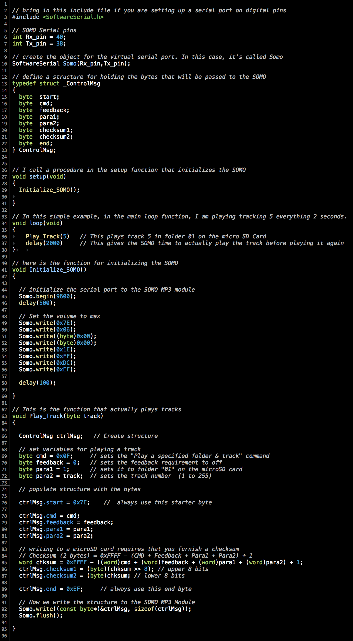
If you wish to copy and paste, grab the code out of this file.
