by Camille | Non-Robot Projects, Workshop Blog
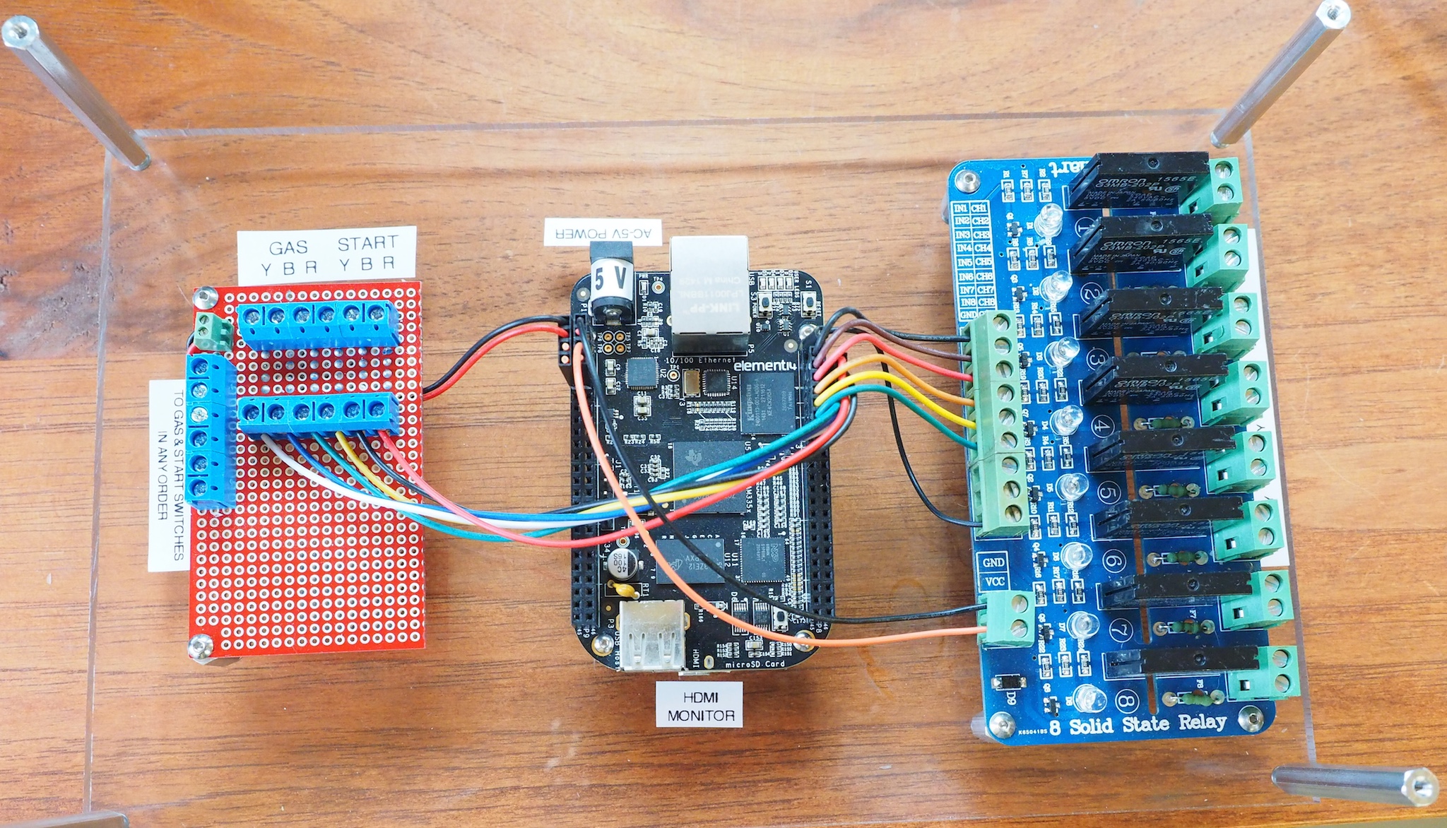
We are working on the electronics for a hands-on museum exhibit that tests reaction time and shows how you can improve their reaction time through practice. The main components of the control unit are a BeagleBone Black, an 8-Channel Relay Board (to control a set of race track staging lights), and a custom-made protoboard with resistors and screw terminals (that take input from the start buttons and gas pedals). The exhibit consists of three race cars. Each car has a start button and a gas pedal. When someone presses a start button, then a set of large staging lights count down Ready, 3, 2, 1, Go! The staging lights are similar to what you would see at a drag racing track. The system then measures the time it takes each driver to press his/her gas pedal. The results are displayed on a large monitor (connected to the BBB’s HDMI port) that everyone can see. If anyone presses his/her pedal too early, then the “Too Early!” light goes on and the screen indicates that it was a false start. The system also includes appropriately-timed drag racing sound effects output through the BBB’s HDMI port to an amplifier and set of speakers. Here is a picture of the control board we made. It will go inside a clear acrylic box to protect it. This is a Rev C BeagleBone Black running Debian Linux. The custom software is written in Python.

by Camille | Workshop Blog
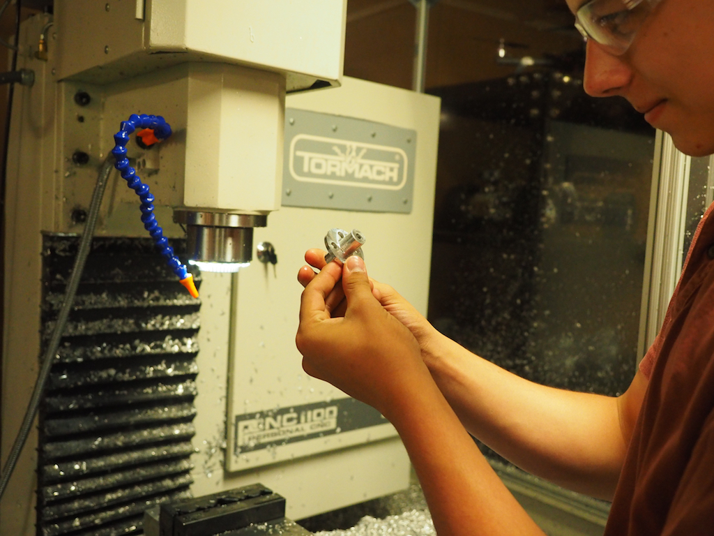
We need six special hubs to attach some very unusual wheels to the 6mm motor shafts on a new robot we’re building. There was nothing commercially available for what we needed, so we designed the hub on the CAD system and we’ve been machining them on our Tormach CNC Mill. Each of us took a turn fixturing the stock, setting up the job with the high-precision probe, and then operating the CNC to make one of the parts. These pictures show our new intern Camille completing his part.
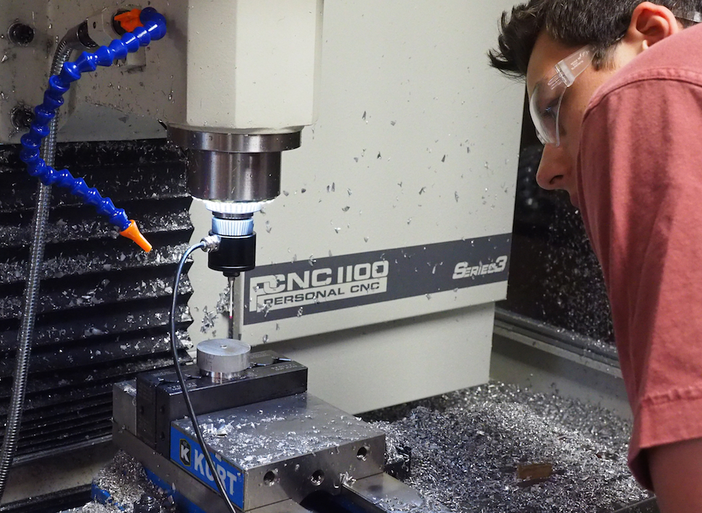
In this picture, our intern Camille has already machined the top of the part, flipped it over, and re-fixtured it into the vise. He is using the red-tipped probe to tell the CNC where the stock is located in the machine. Specifically, it takes readings along the outside diameter in order to calculate the exact x-y position of the center of the cylindrical stock we’re machining. He then uses the probe to set the z-position.
REMOVING THE FINISHED PART FROM THE MACHINE
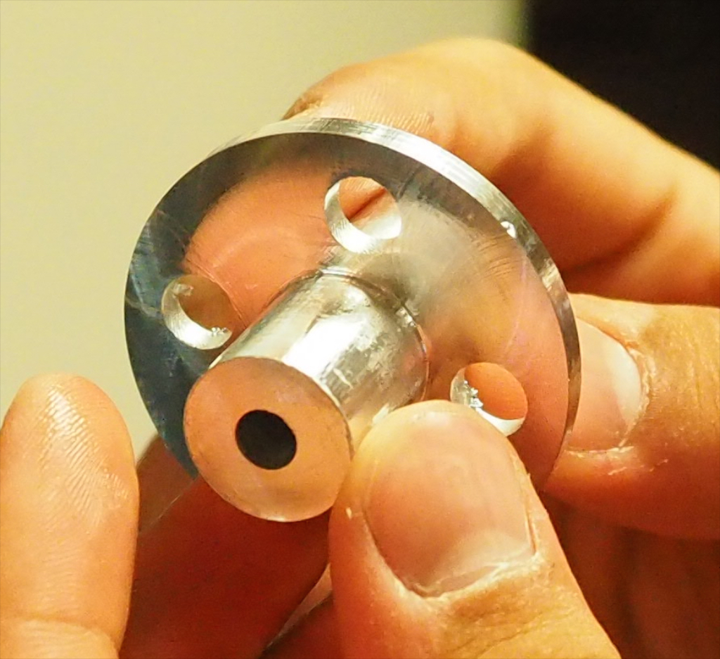
INSPECTING THE FINISHED PART
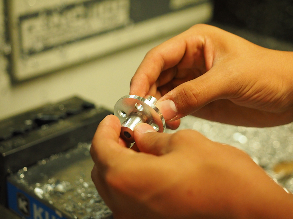
CLOSE UP OF THE FINISHED PART
by Camille | Robots, Workshop Blog
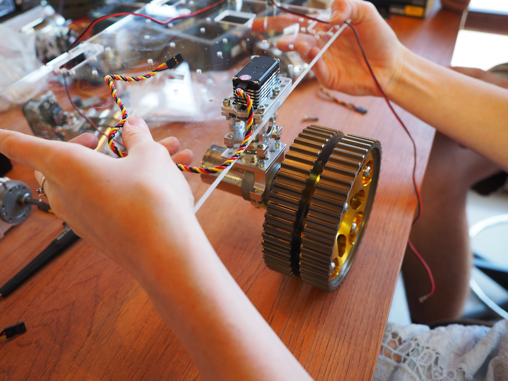
We have taken on a new project to build a compact rover for the New York Hall of Science, something that visitors can drive around in the corridors of the Science Center and that the staff can easily take to off-site activities such as schools and children’s hospitals. The design and construction is well under way. We are also happy to announce that we have a new member at Beatty Robotics. His name is Camille McCollough. He’s a junior at Carolina Day School, where he is taking robotics classes, as well as physics, math, and other curriculum. He has joined our team to learn, gain experience, and lend a hand. Here is Camille building the robot’s pan-tilt turret from Actobotics parts, including a servo, gearbox, and gears:
Camille and Camille working on the assembly of the robot’s front LED “head lights”:
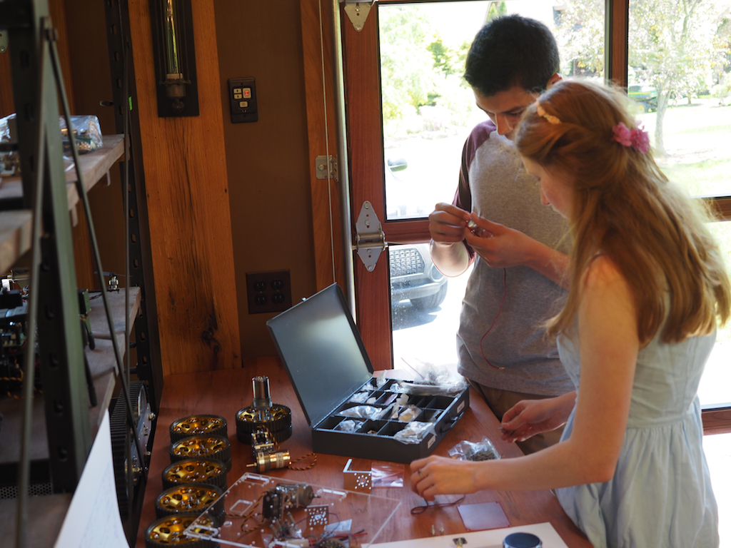
Camille working on the assembly of the sonar mounts, while Camille works on the pan-tilt turret:
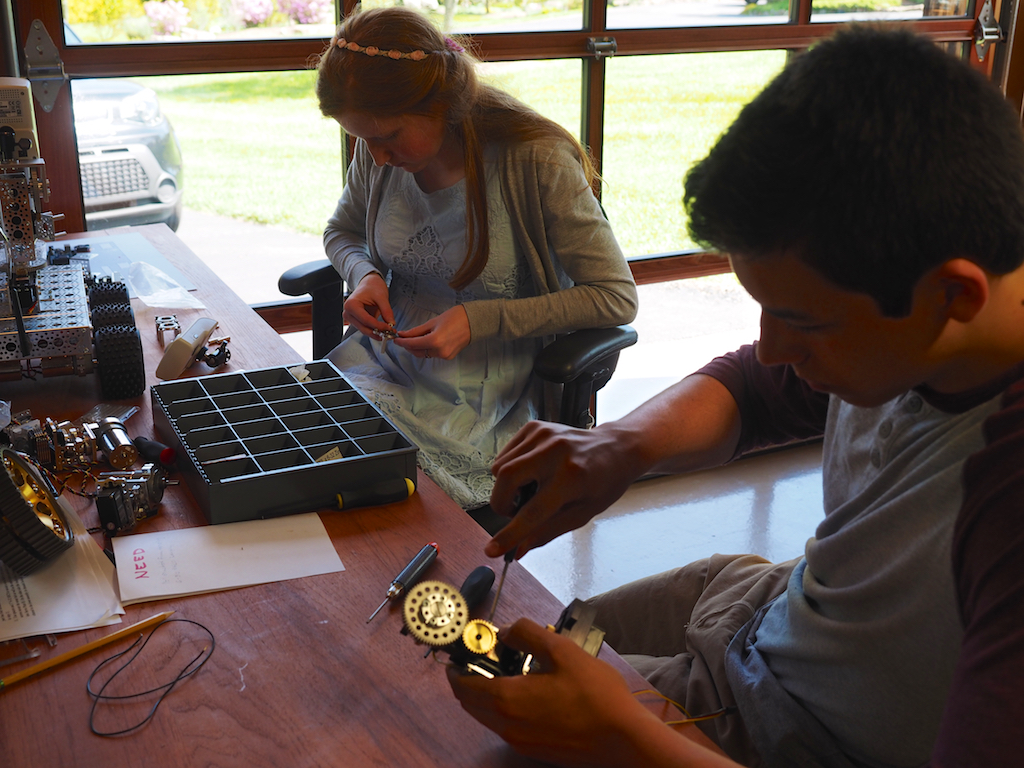
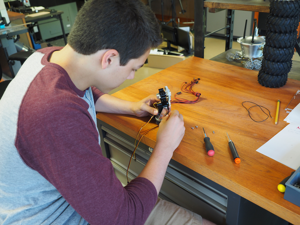
Camille building the first of the six steering assemblies, each of which consists of a servo, servo block, motor, hub, and wheel. We are using a combination of Actobotics parts and our own parts that we made on the CNC.
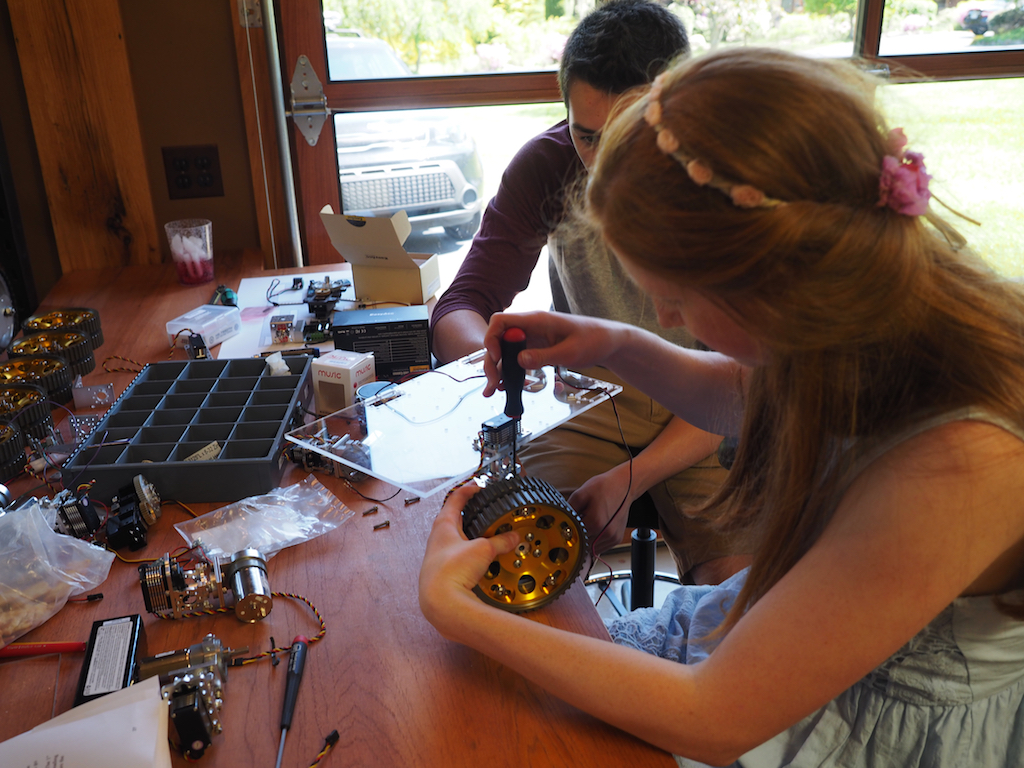
Camille tests the design and assembly of the first steering servo and wheel.
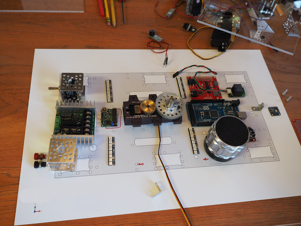
We use a scale drawing of the master plate to plan out where all the components are going to be positioned.
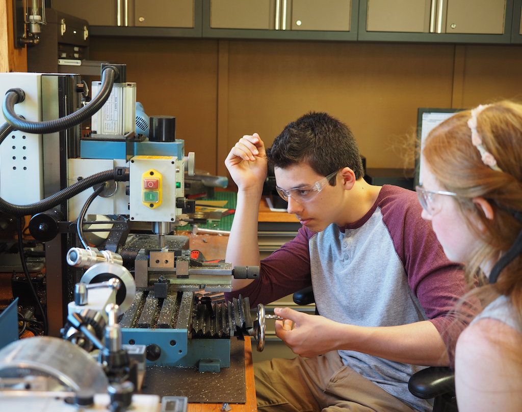
Camille shows Camille how to machine a part of the vertical mill.

Camille machines the next part on the vertical mill.