Machining CNC parts for the telegraph
Today, we worked on the wireless telegraph project. We decided to mount the electronics on brass and copper plates, so we designed the parts on the CAD system and then machined the parts on our home made CNC mill (one of our many projects over the last year). Using the CNC to make project parts was a really cool use of what has become our favorite tool. Here are some pics of the CNC.


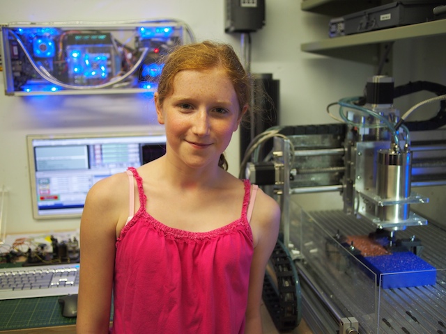
Here is our CNC mill just after machining the copper telegraph base plate. Top left: the computer and electronics box we built. Top center: Cooling tower for the water-cooled spindle. Top right: The 3-phase Variable Frequency Drive (VFD), which powers the 24,000 rpm spindle, is mounted on the wall. Mounted on the wall just below the computer box: an LCD panel for the CNC user interface. Right hand side: The stepper-motor-driven CNC machinery, which is made out of steel and aluminum. You can see the copper part on the blue riser (which is machinable wax). Front center: the system’s keyboard, the emergency stop button box we built, and the jog box (for moving the CNC manually).

A close up of the copper base plate just after it has been machine by the CNC.
Camille showing off her new copper base plate, fresh out of the CNC

We needed two of the base plates (one for each side of the telegraph system), so we machined the second one out of brass instead of copper (using the same CNC file).

Here Camille assembles the telegraph electronics onto the baseplate

Here are the electronics for the telegraph system mounted on the copper plate. The electronics shown here include an Arduino Nano in a screw terminal board, a 7.4v Lithium Polymer Battery, an Xbee Radio, a potentiometer (for tuning the voltage to the Telegraph Sounder), and a small speaker). This copper plate will be mounted inside the base of the telegraph system.


