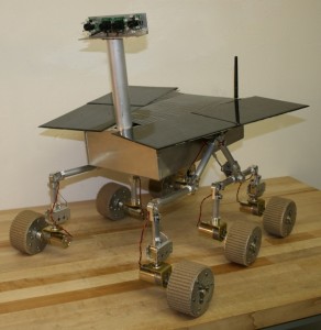
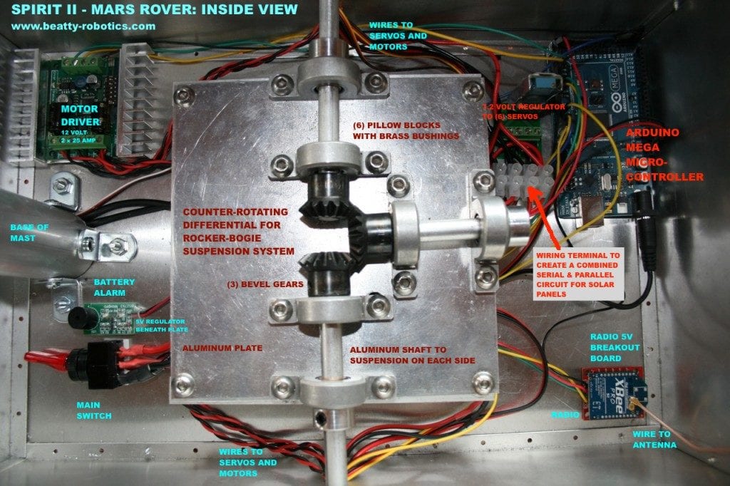
Several readers have requested an inside view of our Spirit II – Mars Rover so that they can see what the electronics look like. We have provided an annotated picture below, along with a couple of external shots.
We have been hard at work on our latest project called Mechatron. To control our Mechatron robot as well as our Mars Rover, we designed and built our own remote control box. We developed our own communication protocol for transmitting commands from the remote control to the robot. On other projects we used iPhones and Playstation remote controllers, but in this case we wanted to build a large, metal box with lots of retro-switches and joysticks.
1. Although it wasn’t cheap, the hall-effect 3-axis joystick was critical for controlling the function of Mechatron’s specialized drive system. We originally tried a traditional analog/resistive/potentiometer-style joystick and it did not work well at all. We thought our whole project was going to fail until we realized that not all joysticks are created equal. The joystick based on the “hall-effect” principle worked perfectly for us.
2. You can’t see it in these photos, but this controller can be charged via banana jacks and re-programmed via a USB jack without having to unscrew and remove the case. The same is true for the Mechatron robot itself.
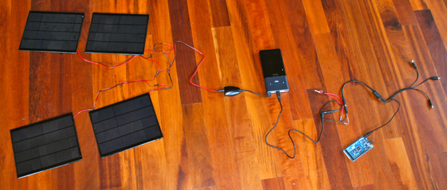
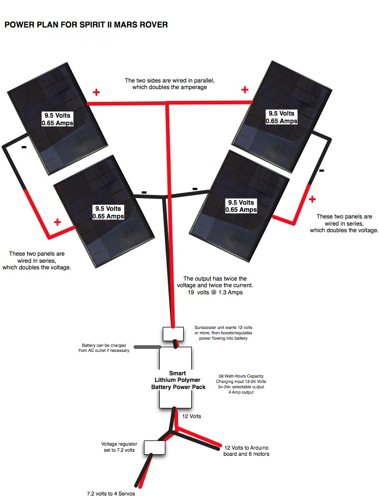
We’ve been working on the power system for our Spirit II Mars Rover, which, like the real Spirit robot on Mars, will be solar powered. We plan to use four small solar panels. Each one is about 7″ x 9″ and delivers about 9.5 Volts / 0.65 Amps / 5.2 Watts.
We wired two pair of panels into a series circuit to double the voltage of the output, then wired the pairs together into a parallel circuit to double the current amperage. We the combined unit to a little voltage regulator that feeds a lithium polymer smart battery, which in turn will feed the electronics, motors, and servos of the Mars Rover robot.
Today we wired the panels in series/parallel, hooked everything together, and powered our main Arduino microcontroller. It worked and it was very cool!
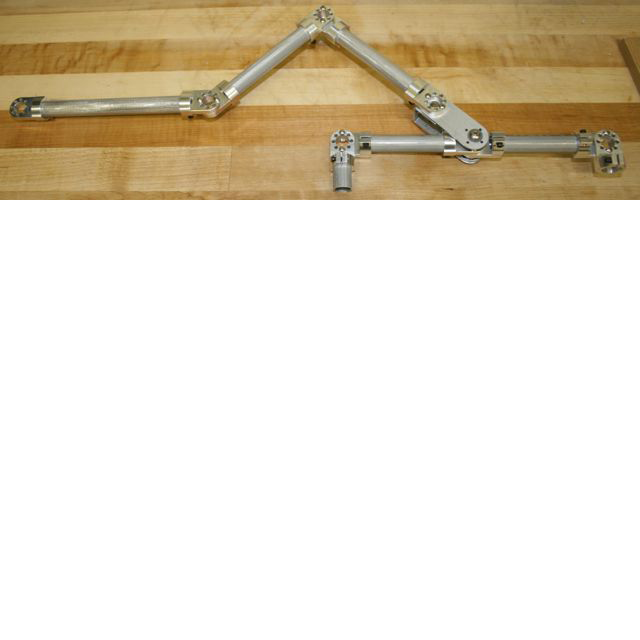
We have been working hard on the rocker-bogie suspension system for the Spirit II, our Mars Rover. In this picture, the front wheel will be attached on the left side. The two back wheels will be attached on the right side. The two back wheels will be connected together by a tube that pivots on its center. The entire thing pivots on a central shaft (connected at the junction second from the left) that goes through the counter-rotating differential to an identical chassis frame on the other side of the robot. We are building the chassis frame out of .625 aluminum tube, tube connectors, and aluminum plate. It takes a bit of imagination at this point to visualize how this is going to become a Mars Rover, but it’s coming along. If it all actually works, we’ll be amazed.
We are currently building a rover similar to the Mars Rovers Spirit and Opportunity, which we have always loved (but have been way outside our skillset in the past).
We have been studying the details of the rovers, their electrical systems, chassis, wheels, and so on. Ours won’t be exact, of course, but hopefully, if all goes well, it will be a nice working model, including the solar panels.
One of the most unusual and characteristic elements of the Mars Rover design is what they call a rocker-bogie suspension system (http://en.wikipedia.org/wiki/Rocker-bogie), which is intended to help the rover go over rocks. This system involves six wheels, with a special interconnection between the various wheels so that at least one or two of the wheels on each side are on the ground at any one time, even when going over obstacles. It took a while to figure it out, but this design requires a connection between the wheels and each side such that when the wheels on one side go up over a rock the wheels on the other side go down and vice versa. NASA uses what they call a “differential” (although it’s not the same as a car differential).
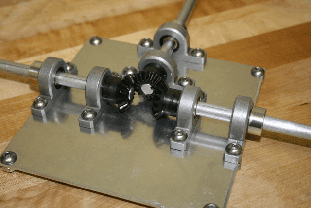
Anyway, we couldn’t find a counter rotating differential that met the requirements, so we decided to make made one. We’ve attached a picture. The plate, pillow blocks, and shafts are made out of aluminum. There are three bevel gears, which are made out of steel. This gear box will go inside the center of the robot’s main box directly between the wheel sets on each side. The way we’ve meshed the gears together creates a counter rotating shaft so that when one side goes up the other side goes down.