by Camille | Workshop Blog
A few subscribers have asked about laser and the thermal array sensor on the new Mars Rover, so this post is dedicated to that:
We needed to add a targeting laser and a thermal array sensor to the Mars Rover robot, so we experimented with different wavelengths of lasers and types of lenses. After looking at the results of our tests, we decided on a 532 nanometer laser (which is bright green in color), with adjustable 5 to 25 milliwatts of power, and a 38-degree line-generating lens.
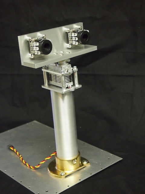
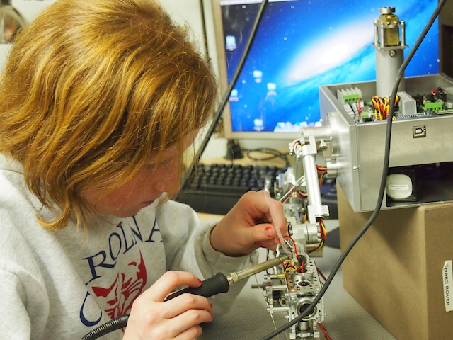
We plan to use a TPA81 Thermopile Array sensor to scan the temperature of the objects that are out in front of the robot (a few feet or a few yards away). This particular sensor provides an 8 x 1 array of eight temperatures corresponding to eight points from left to right in front of it (about 40 degrees across). But it’s hard to tell exactly where it’s pointing and which objects it’s measuring, so we plan to use the laser to identify the scanning zone. We cobbled together a prototype and our initial tests of all this worked well, so we moved into the final build stage and mounted it into the robot. The key was to make sure that the laser was lined up with the thermal array sensor, which necessitated a special mounting mechanism.
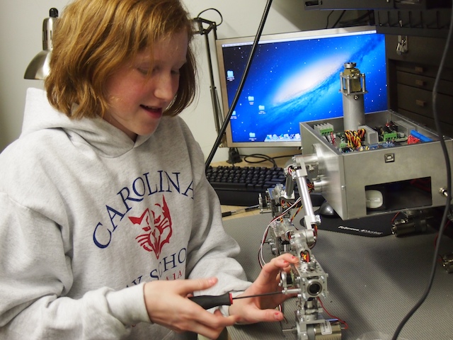
Here I am with a devilish grin as I experiment with different types of lasers. I decided on the green laser because it’s strongest, easiest to see, and “just plain the coolest.”

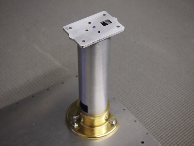
I used my favorite tool, the vertical mini mill, to do some machining to modify the laser mount. We then drilled and tapped various threaded holes into the mount.

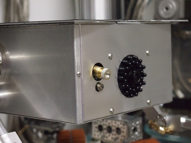
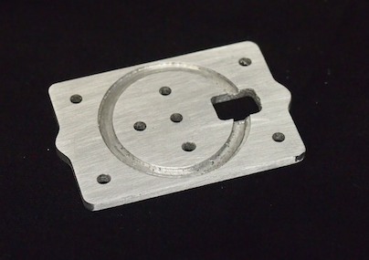
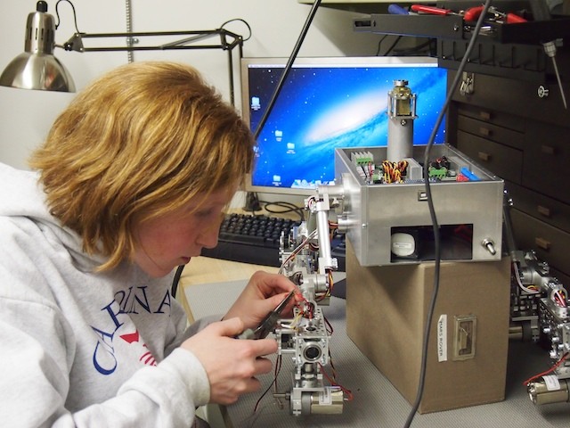
Here is the finished Laser Mount. The laser fits in the large hole in the middle and is held with a set screw through the threaded hole on the side. The threaded hole on the bottom is used to attach the mount to the articulating arm. The threaded hole on the face (top in the picture) of the mount is used to attached the Thermal Array Sensor. This way the Laser and Thermal Array Sensor are screwed together and always pointing in the same direction/angle.

Here we have mounted the Target Laser (on top) and the Thermal Array Sensor (on the bottom) into the front of the robot (front plate removed). You can’t see it too clearly in this picture, but the laser mount sub-assembly is mounted on an articulating arm on a base so that we can adjust the pointing angle/direction. Please note that the line generating lens is tilted in this picture and needs to be adjusted so that the visible lines in the lens are vertical (which is weird because it generates a horizontal line).
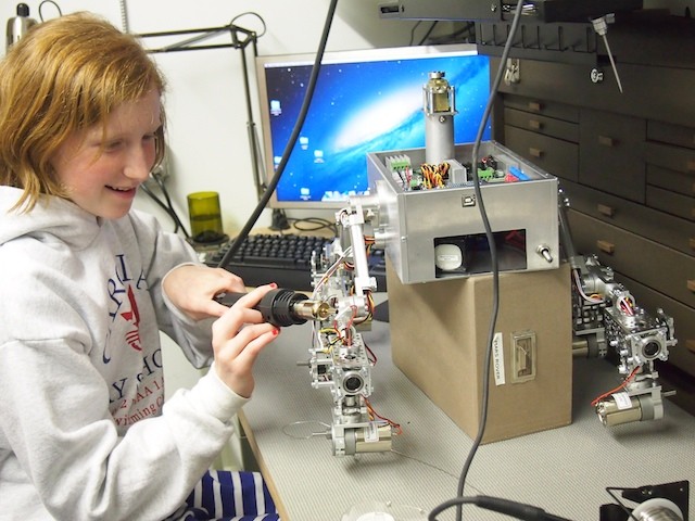
The finished result. We’re ready to scan some alien Martian life ! (Or at least some warm rocks!) 🙂
by Camille | Workshop Blog
We’ve been busy working on the new Mars Rover. Over the last few days we’ve been focused on the chassis, the thin-film solar panels for the top, the mast, and aligning the servos for steering. Pics below.
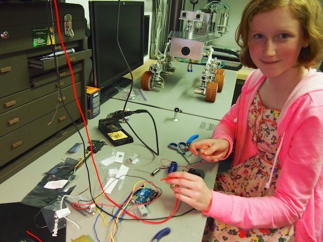
Here I am using my new power driver to work on the robot’s chassis. This is now my favorite tool.
Working on assembling the solar panels that will cover the top deck of the Mars Rover.
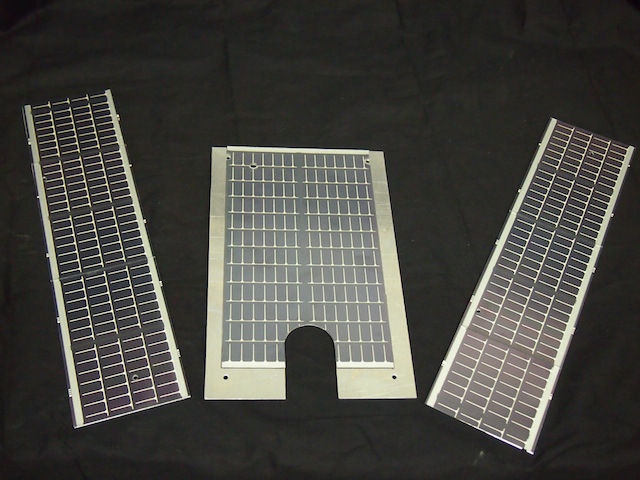
The completed “solar wings” and top deck. These are actual thin-film solar panels attached to custom-machined aluminum plates.
We ran into a particular challenge when it came time to build the mast. In the end, we decided to design and machine a custom servo plate using the CNC. The top of the plate will hold the pan servo. The bottom of the plate will hold the shaft tube (using a circular slot).
The custom servo plate mounted on the mast. The plate is held down with a threaded rod that goes down through the mast and threads into the bottom of the rover.
Here is the completed mast assembly. From the bottom up: The robot’s bottom plate, the mast flange, the mast tube, the custom servo plate, the pan servo, the top servo plate, the servo horn, and the mast head, which is made out of two custom machined plates of aluminum.
In order to align and calibrate the steering servos we created a special, full-scale drawing that indicates where the wheels should be at each of the various steering positions. This really helped center the servos properly.
by Camille | Workshop Blog
Here are some pictures as we continue work on our new Mars Rover.

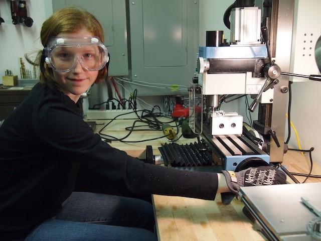
I’m using the vertical mill to modify an aluminum part for the Mars Rover. Cutting, drilling, and machining metal is my favorite area of work now. I’m turning into a good machinist.
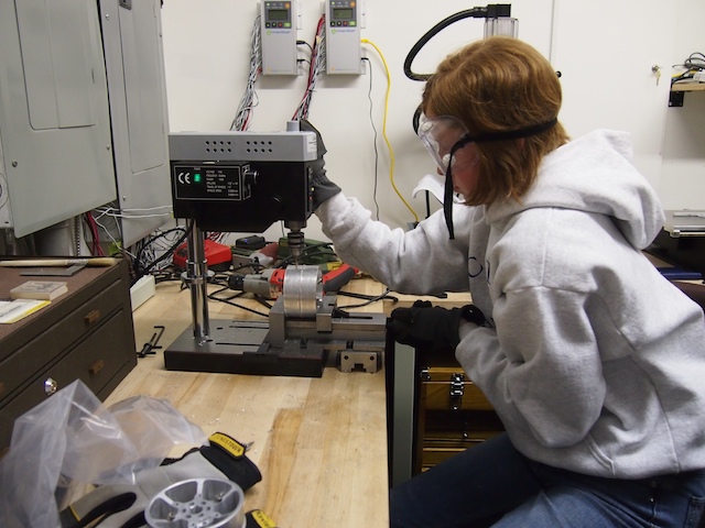
I’m using our mini drill press to drill holes onto the metal wheels in preparation for tapping the threads.
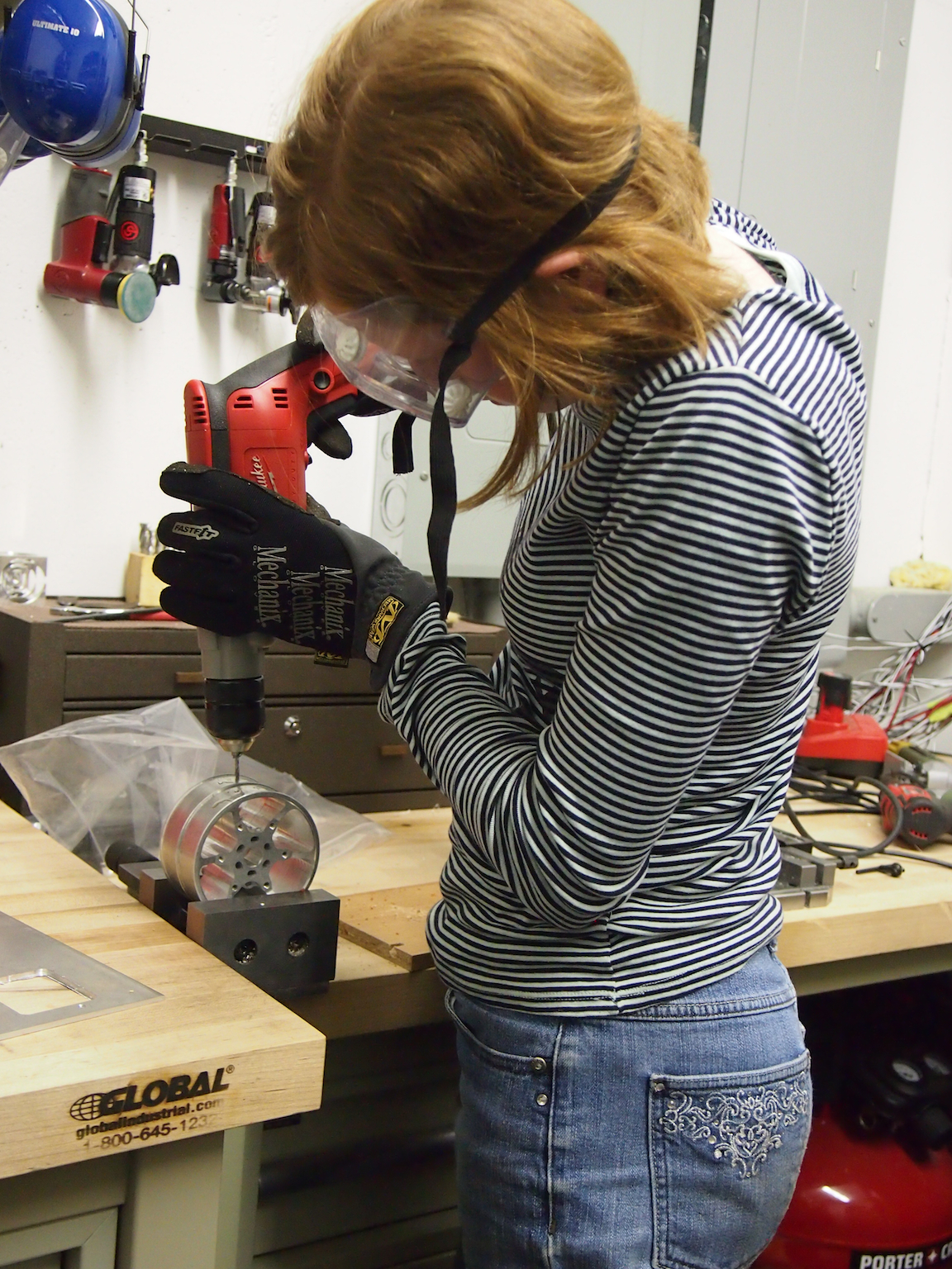
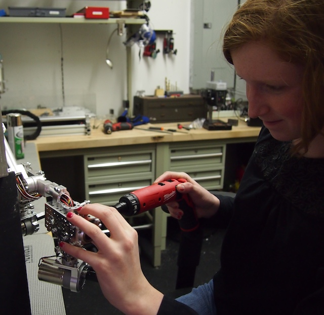
A new skill: I use our largest Milwaukee drill to tap 6-32 threads into the holes she drilled into metal wheels. The threaded holes will be used to secure the tread to the wheel (we don’t like glue). Tapping threads is very tricky (it’s very easy to snap the tapping bit), but she does a splendid job.
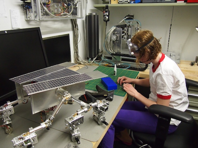
I’m mounting a side-firing sonar sensor on the the rocker-bogie suspension system. She’s done most of the mechanical construction on the robot.
I’m feeding wires through the chassis tube.
After fishing the wires through the chassis tubes, I solder the power, ground, and signal wires to the sonar sensors.
I use the electric heat gun to complete the heat shrinking on the wires she just soldered. (Red nail polish is optional when heat shrinking in our workshop, but always a plus!)
Slowly but surely, we’re making progress. We’ve completed all the wiring and soldering for the sonars, motors, and servos on the chassis, and we’ve assembled and installed the wheels. We sill need to complete the rover’s top, install the solar panels, build the mast head, and many other elements. Stay tuned.
by Camille | Workshop Blog
The Mars Rover needs to detect infrared in its camera so that visitors can identify infrared-emitting rocks that are hidden in various spots in the Mars Exhibit. We have completed a series of experiments to confirm that this part of the Rover is working properly. Pics and explanation below.
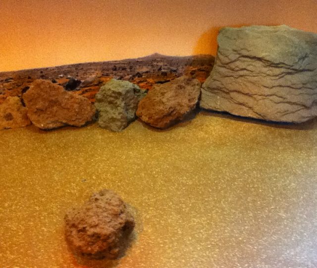
The Mars exhibit has many Mars rocks. A few of the rocks are hollow and have an infrared lamp inside so the rock emits infrared energy. The visitor’s objective is to drive the Rover around the Mars exhibit and find the hidden infrared-emitting rocks. (On the real Mars, infrared-emitting rocks indicate that the rocks may have been formed in liquid water, and therefore may be a clue to past life on Mars)
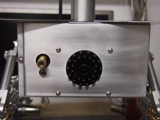
The Mars Rover is equipped with the inner core of a high-quality 640×480 WiFi camera (the Sharx Security SCNC2700). The video camera looks straight ahead from its front panel. By sending the camera a special web-post (thank you to the folks at Sharx for their special help on this), we can programmatically turn the camera’s IR cut-filter on and off, thereby switching the camera between “Normal Camera” mode and “Infrared Camera” mode.
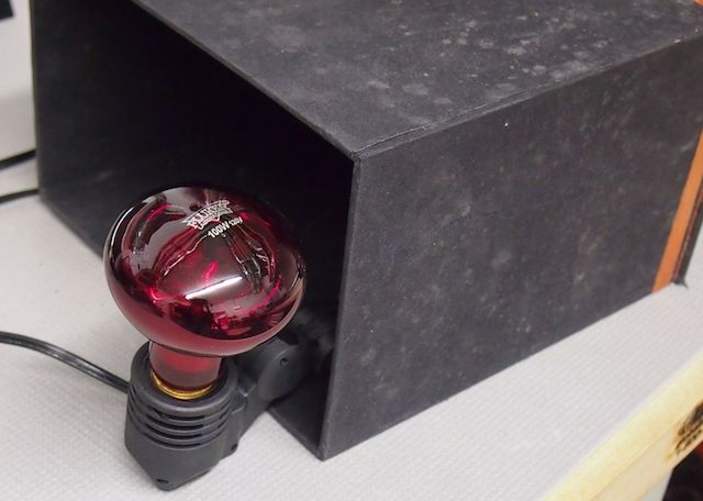
We didn’t have a “Mars Rock” to work with in our workshop, so for this experiment, we placed an infrared lamp inside a black box.
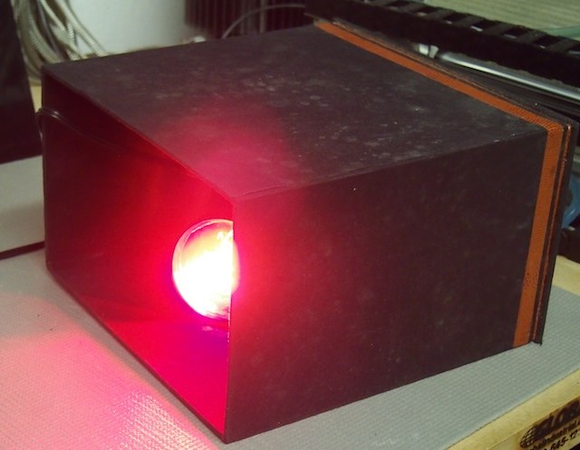
We turned the infrared lamp on.
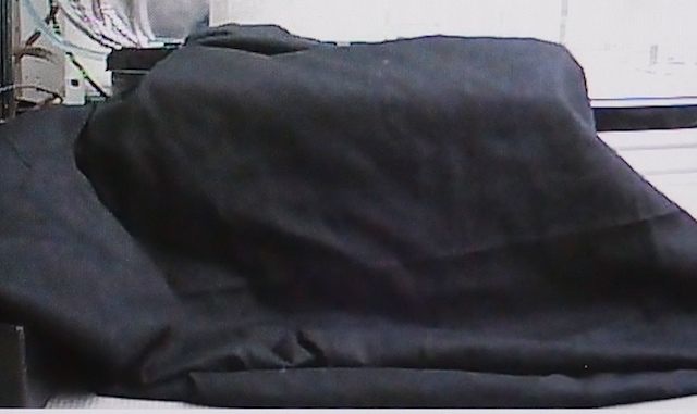
We then covered the box with six layers of black muslin cloth. To the naked eye and when viewing it through the video camera in normal viewing mode it looks simply black. This is serving the purpose of our “Mars Rock” for this experiment. This is a picture of what we see on screen in the camera’s video stream. It looks like normal black cloth.
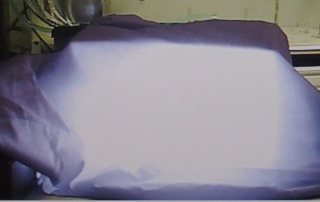
We then turn on the “Infrared Camera” mode. Just as we hoped and theorized, the black box now appears as bright white in the camera. So, when visitors to the exhibit switch the Rover’s camera into “Infrared Camera” mode they will be able to easily differentiate the infrared-emitting rocks from the normal rocks.
Special thanks to the folks at Sharx Security for not freaking out when I told them I was tearing one of their cameras apart piece by piece, integrating it into our robot, and sending it to “Mars.” They were very helpful in providing the technical information we needed to get the camera to do what we needed it to do. All indications are that it’s going to work very well for us.
by Camille | Workshop Blog
We’ve been making good progress on the Mars Rover. Today, we used our new milling machine to put the finishing touches on the hubs we are using to mount the central chassis shaft to the rover’s main box. By completing the two hubs, we were then able to assemble the two sides of the rocker-bogie suspension chassis with the main box, which in turn allowed us to begin soldering the servos and sonar sensors. It’s really starting to come together now. Pictures below.
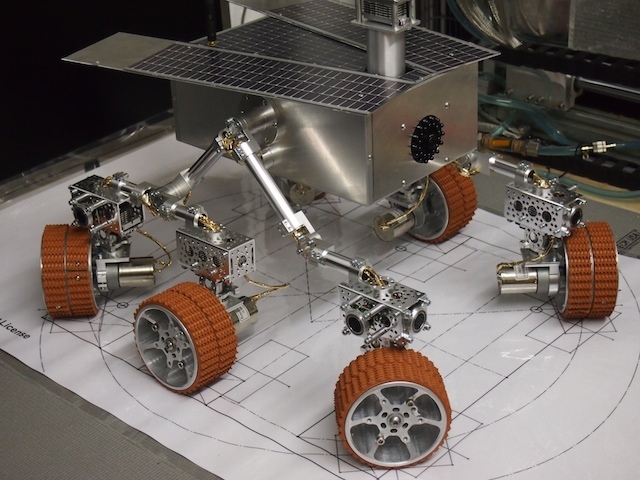
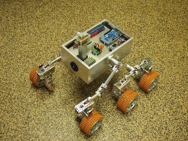
The Mars Rover is starting to take shape. The two sides of the rocker-bogie suspension system have now been installed on the main box. We put one of the wheels in place to show what it will look like. The motor, servo, and two sonar sensors are soldered on the front wheel, but not the back two (thus the hanging wires).
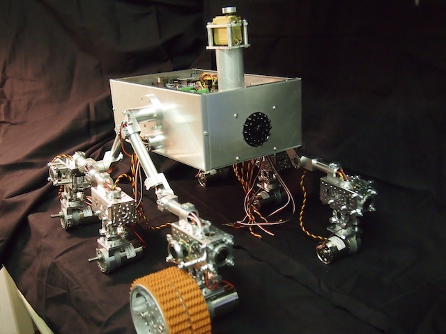
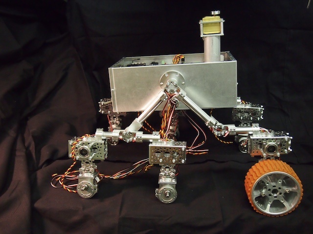
This shot shows the front corner of the partially assembled Mars Rover. Note the camera mounted on the front plate and the partially assembled mast.
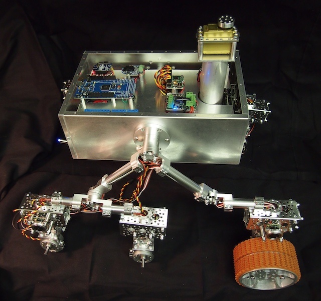
This view provides a glimpse of the electronics inside the main box.
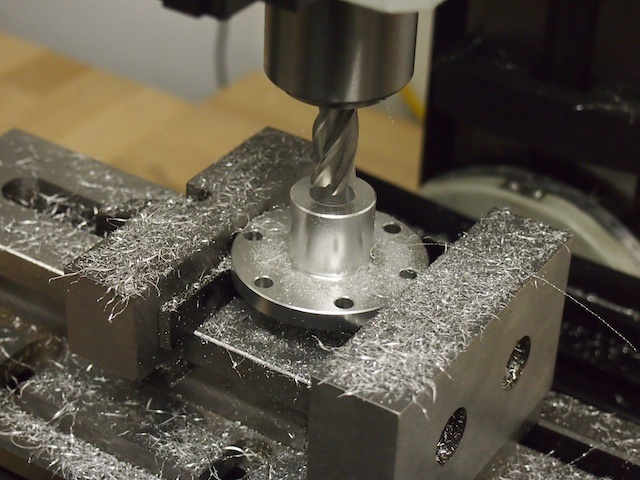
Here we are using our new vertical mill to machine the center hole of the hub.
