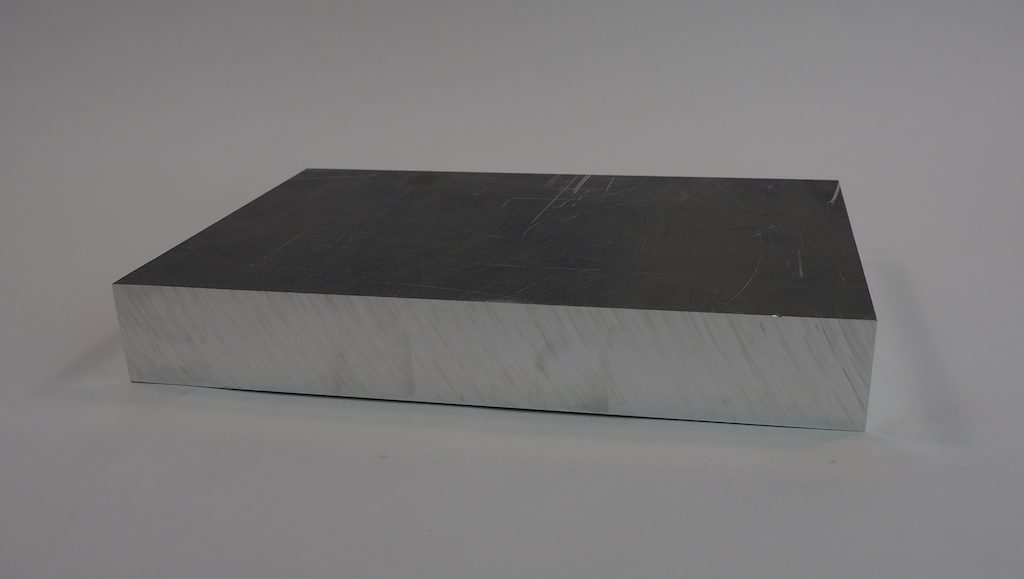
We’ve been working on a fun new robot we call Metalbot. Our goal was to build an autonomous rover with a unibody design that was machined out of a single block of metal. We started with this 13” x 9” x 1.75” block of 6061 aluminum:
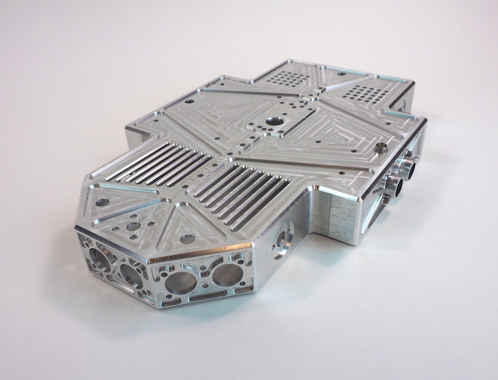
When the machining was done, the robot’s body looked like this. It’s a hollowed-out shell that is about 1/8” thick with holes, slots, and pockets for the motors, LEDs, sensors, and other electronics.
Once Metalbot was assembled with the internal components, it looked like this:
What do you think? We think it’s pretty cool looking. Do you like it?
Work-in-Process Pics
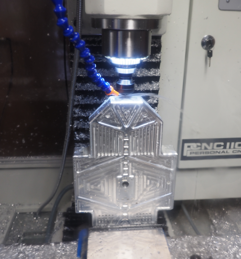
In this first picture (which was taken through the polycarbonate enclosure), we clamped the part vertically in the vise and we’re using an 1/8″ end mill to machine the detail on the front of the nose. In a previous operation we clamped the stock flat and machined the top of the robot, so that work is already done. Because this part has features on every side, machining it required us to clamp the stock in the vise in 8 different orientations: top, left side, right side, back, front, 45-degree left nose, 45-degree right nose, and bottom.
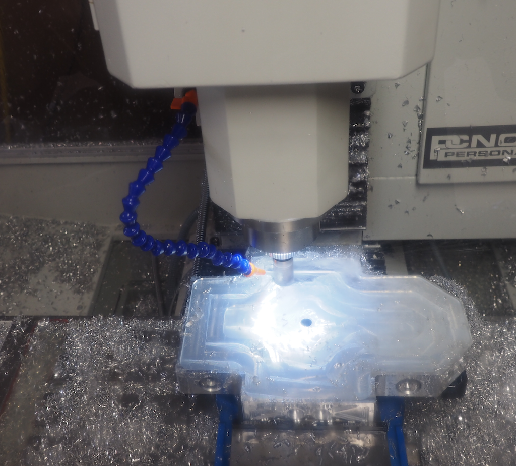
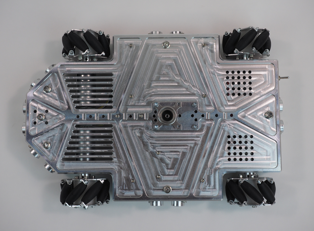
In this next picture, we’re on the last setup, machining out the large pocket on the underside of the robot. This turned the aluminum block into a 1/8” thick shell. The large pocket appears to be glowing because the ring of LEDs we installed around the mill’s spindle are shining into the coolant that has filled the pocket. We’re using a 25mm (.98”) modular end mill here, which is designed to remove material fast. Of course, there were a lot of metal chips, but it’s important to remember that aluminum is easy and efficient to recycle.
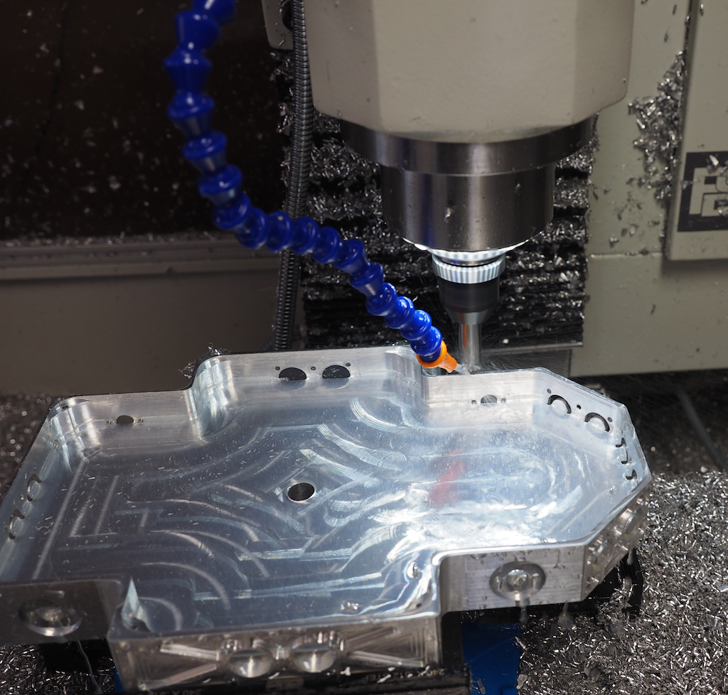
In this picture we’re half way done digging the pocket and we have the machine take a break from the hard work to chamfer the outside contour:
Once the body is machined, we screwed in the wheels, motors, and electronics, which are screwed upside down on the underside, where they are easy to access when the robot is turned over. We will install a bottom plate later.
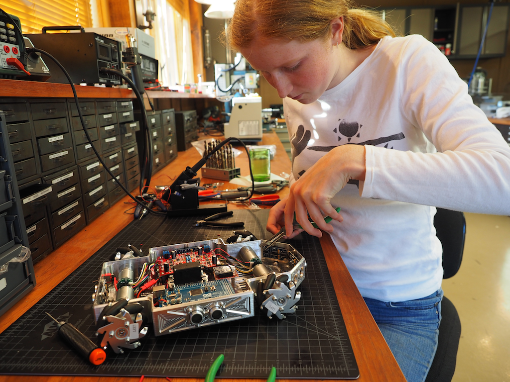
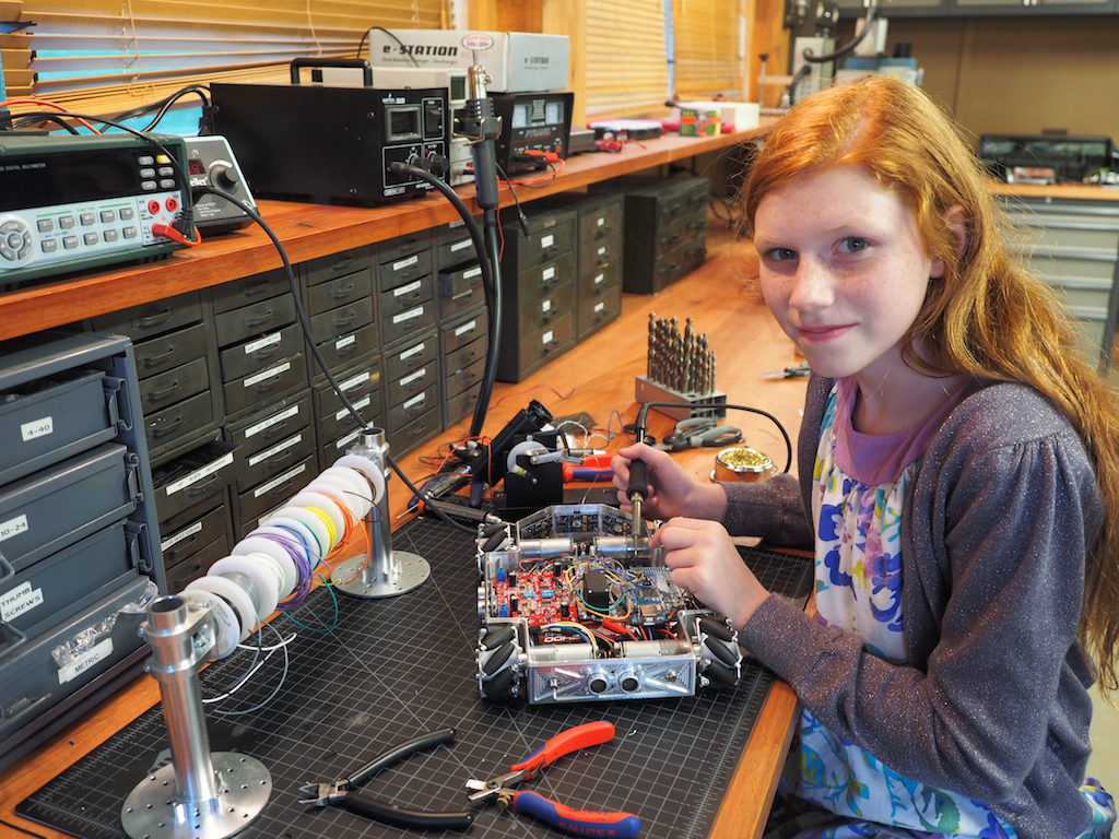
Then we did the wiring and soldering:
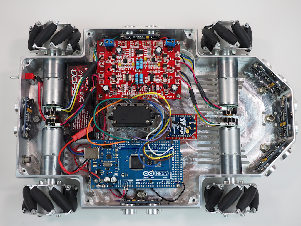
Here is the underside of the robot with most of the electronics installed. We’re using an Arduino Mega and a 4-channel Motor Controller, along with 4 Pololu gear motors to drive the mecanum wheels, which will allow the robot to strafe. The robot is also equipped with 6 Ping ultrasonic sensors for autonomous object detection, a LIPO battery, a main power switch, 6 NeoPixel RGB LEDs to indicate the state of each sensor, an Xbee Radio, and a panning servo (black thing in the middle). The robot will also be equipped with an MP3 module and speaker for sound, but those haven’t been installed yet.
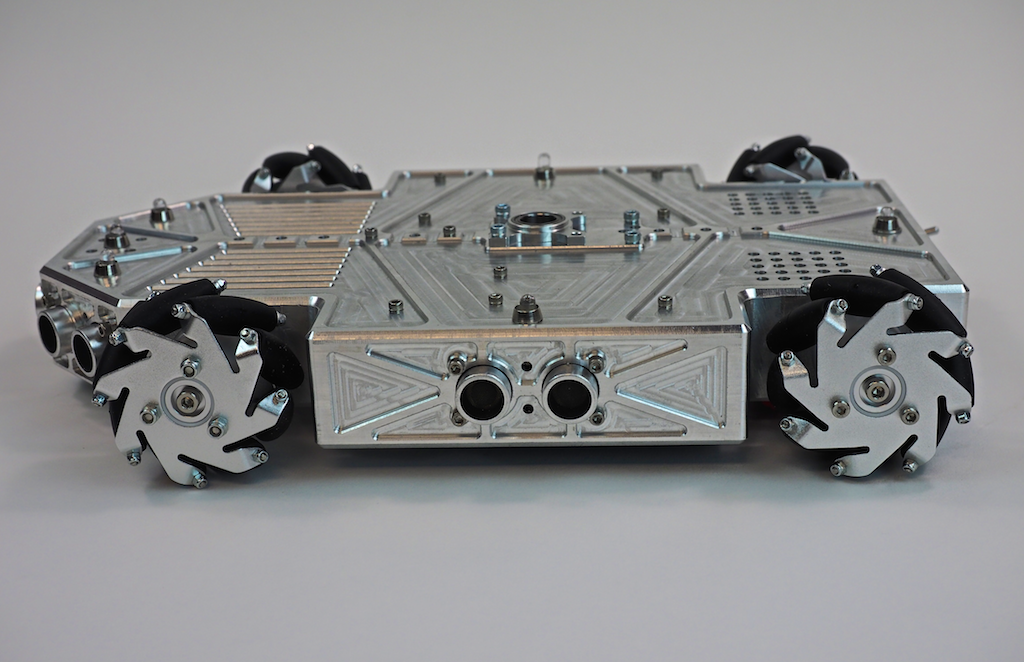
The robot’s finished body is 8” wide and 12” long. The rover can be fitted with either the mecanum wheels shown or CNC-machined conventional wheels (not shown). Our original goal was just to machine a cool looking rover out of a single piece of metal, but as we went along, we decided to add some flexibility into the design for future enhancements in case we wanted to do more with it. The robot has been designed with a central spine of holes and ridges for attaching future add-ons, including a servo mounted in the center, which will support a pan-tilt turret for a camera, gun, or arm. We have designed the pan-tilt turret to utilize the Actobotics ecosystem, but other pan-tilt mechanisms could also be used. There are also holes on the front and rear of the top deck that are compatible with the full range of Actobotics components such as brackets, hubs, and channels, which really adds a lot of flexibility.
The next step is to work on the sensors and software programming. With its mecanum wheels, it should be able strafe like a champ very soon.
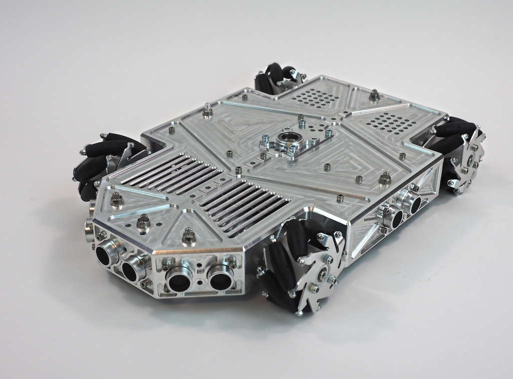
Here are a few more pictures of Metalbot so far. Let us know what you think. Do you like the overall design?


Most impressive and awesome !!!!
Excellent work and a fine job of documenting your projects. The photography is well thought out and very professional.
It is great that you were able to purchase a Tormach CNC Mill. I am anxious to see what you can do with it.
I’ve been reading your posts for about a year now. Your family is an inspiration.
Very cool. You are extremely good at blending form with function.
Another amazing creation!
What is a good way to get into learning CNC? Is there a cheap, and at least decent quality, entry level home CNC machine (kit) to learn on? What would you recommend?
Cheers,
Andrew
Awesome! It immediately brought the APC from Aliens to mind: http://i265.photobucket.com/albums/ii221/trentonSA/Army%20Forums/AliensAPC.jpg
Excellent work! Your projects bring me many possibilities to pick up my childhood dream : to design and make robot.Thank for sharing what you made……:-)
Beautiful robot Camille and team! Must have really been a challenge to mount the block at 45 degrees for CNcing. I was just wondering though, given how low the ground clearance is, the robot will probably only be able to ride over very smooth terrain if I’m not wrong? Have you considered adding in a suspension system as well?
Thanks, everybody. Aditya: It was indeed a bit tricky to mount the part at 45-degrees to machine the nose. Regarding the underside clearance. You are right that the robot is designed for smooth surfaces. In particular, it’s designed as an indoor robot (carpet, wood, tile, etc.) or a pavement robot. It’s not suitable for grass and rocks. I have found that in general mecanum wheels work best on man-made smooth surfaces rather than rough terrain. Having said that, the design could be tweaked a bit to support large diameter, knobby tires for outdoor use, but on this iteration we were going for a low-to-the-ground look for an indoor robot.
Thank you, for sharing your ideas and progress. You are an inspiration to those of us trying to teach the basics.
Wow! Awesome bot. Wish I had all the tools you have for machining your own parts. Which Pololu gear motors did you use? Looks like they have encoders.
Thanks, Laura. We appreciate it. Those are the 47:1 25Dx52L HP gear motors from Pololu. Excellent, tough little motors. Initially I thought we would use the encoders (and definitely wanted the option just in case), but encoders turned out not to be necessary, so the encoder wires aren’t hooked up.
I would like to know if you guys sell the body.. or at least the cad file?