We are super excited to introduce Sojourner, our newest robot. The original 1997 NASA Sojourner was the very first...
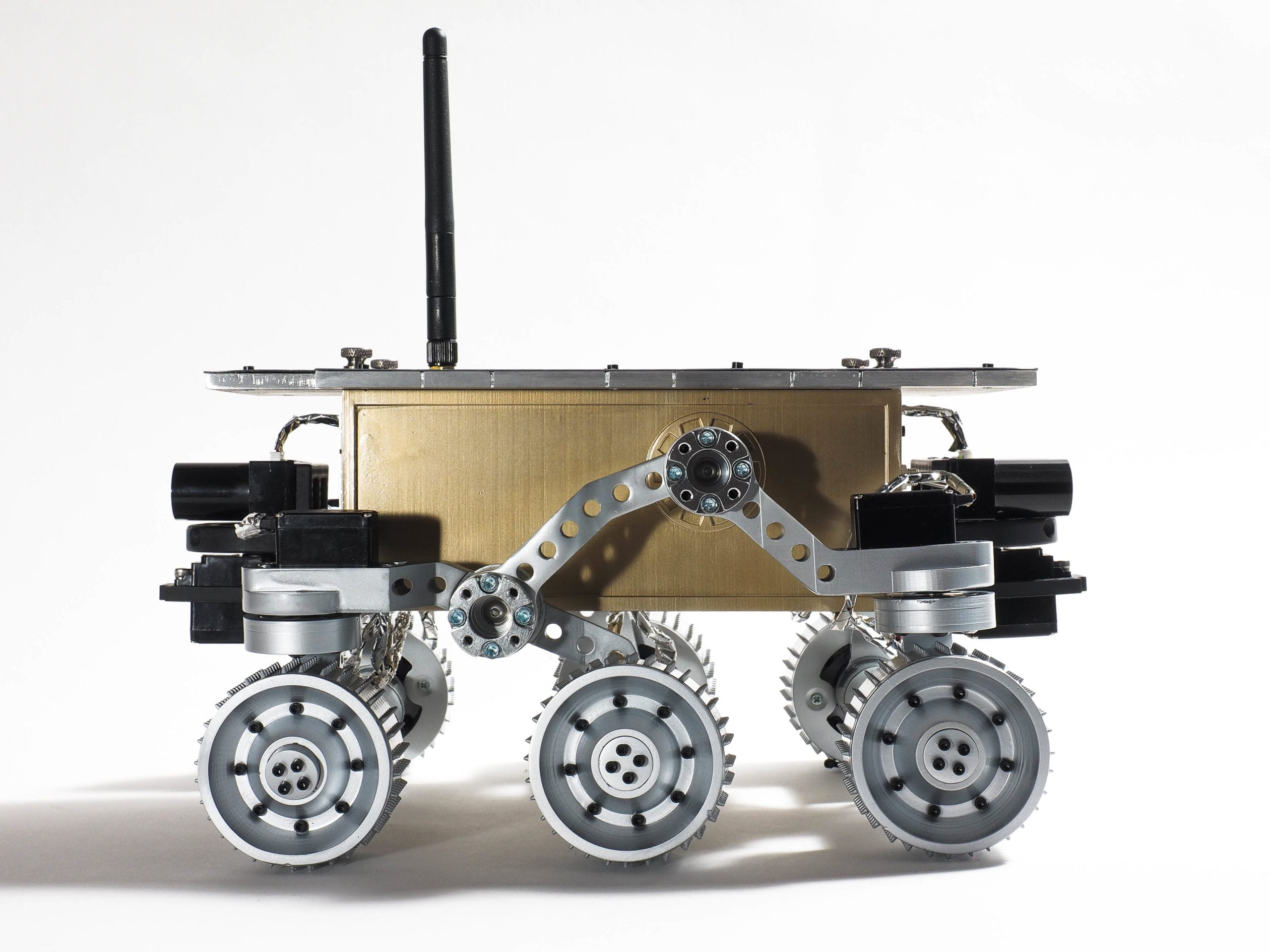
We are super excited to introduce Sojourner, our newest robot. The original 1997 NASA Sojourner was the very first...
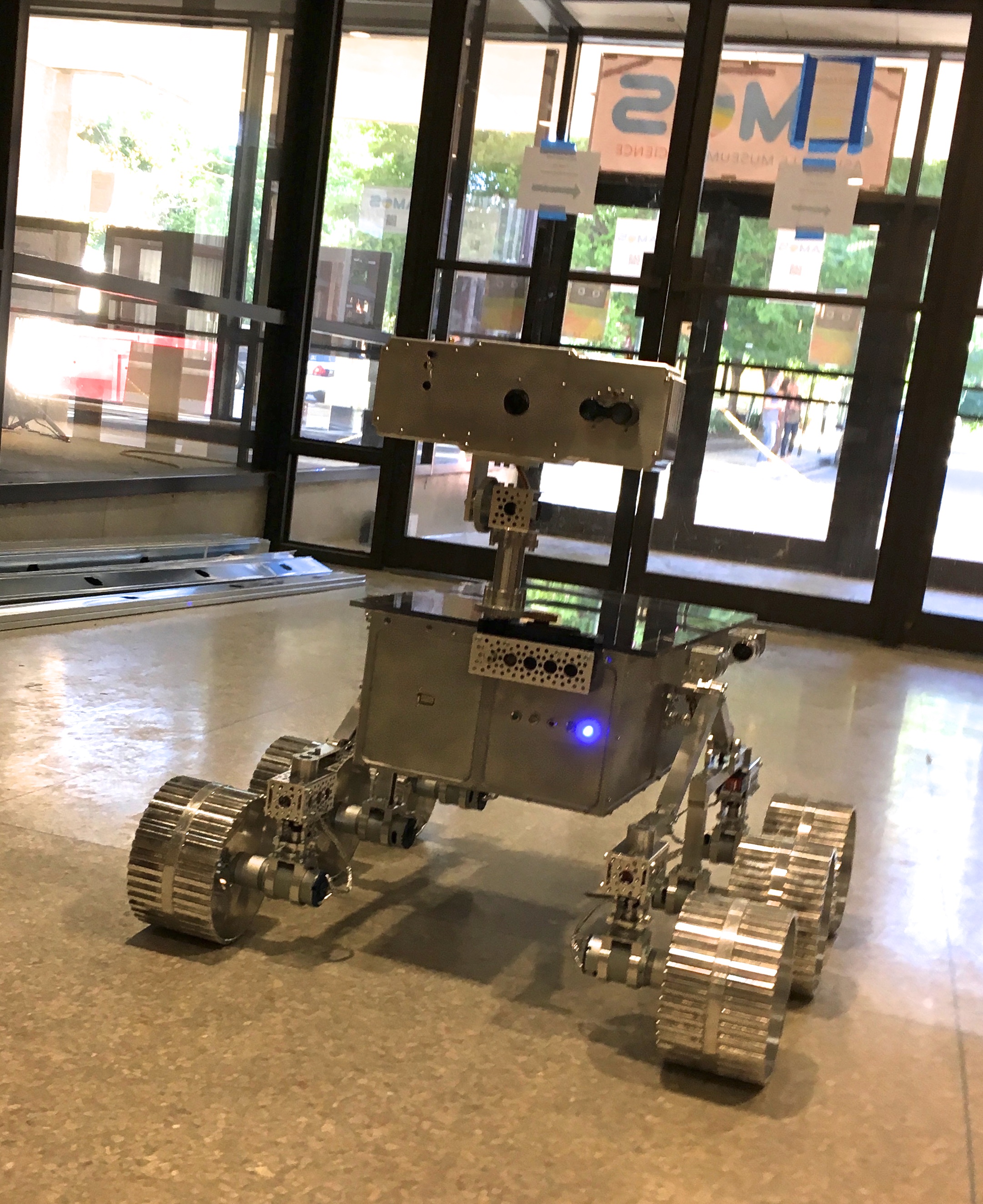
In this video, we're taking the Lunar Rover on a quick visit to the Asheville Museum of Science (AMOS) to test it out...
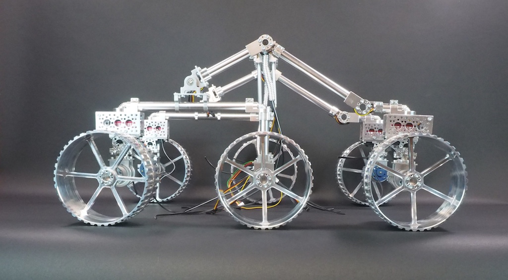
SpaceLS, a rocket company in the UK, has asked Beatty Robotics to team up with them to pursue a mission to put a rover...